Hello,
There should be more exchange of ideas on how to position the different boards.
If power supply is that important why isn't there more info on how to make it work as perfect as possible.
Just adding more caps is stupid if you don't pay attention to details.
The power supply with the biggest caps is the most important one so that one should be as close as possible to the " consumer" . Try exaggeration to make things clear. You have a basement that you don't use, fill it up completely with a supercaps, drill a hole in your floor and have an eight feet cable and attach it to that flimsy connector.
You could " organize " your board collection in such a way that the cable from supercap to Q7 is let us say 100 millimetres maximum. If it is more you are doing something wrong.
If your Raspberry is not separate In it own housing and you are not a budget something is wrong.
If you don't own a dddac something is wrong.
Greetings Eduard
Hello,eduard@
I have removed the 7810 regulators, and have 10vdc on input mainboard. Rock steady for many years.
So why all the big power boards?
Hello,
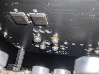
I just go a photo from a respectable member having doubts about the soldering quality of this supercap to a board.
Probably the brown stuff is some flux.
I advised him to get a desoldering station to remove the solder, clean the board and do it with a proper tool.
How big is the percentage of boards out there that look like this?
Greetings,Eduard
Attachments
This is extremely helpful! Gives me a good reference point.Hello,
I just go a photo from a respectable member having doubts about the soldering quality of this supercap to a board.
Probably the brown stuff is some flux.
I advised him to get a desoldering station to remove the solder, clean the board and do it with a proper tool.
How big is the percentage of boards out there that look like this?
What is the yellow lining below the solder?
I observe a particular phenomenon and want to ask if any of you observe the same:
My DAC stack is:
ReceiverPI DDC
FiFoPi Q7 with SC-Pure clocks powered by UcPure
Dual Mono DAC HAT MKII
OPA861 I/V board powered by LinearPI + UcConditioner
The FiFoPI Q7 is connected to the continuous power from UcPure so SC-Pure clocks are powered all the time. The rest of the power supply is turned on when I need it.
What I observe is that initially, after switching on, the whole stack sounds worse compared to how it sounds after it has "warmed up". After about 30-60 minutes, it starts to sound right.
Does only one else experience something similar? What could the reason be?
Marcin
Hey everyone,
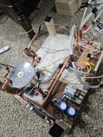
Been hard at work at my build. Here is a teaser. Every component has an additional copper enclosure that goes onto each, full encapsulating each component.
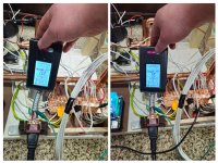
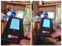
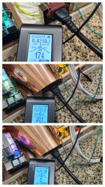
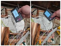
I would like to share some images to also show the importance of grounding. The EF noise gets into everything, and every piece of gear (ucpure included) spews this into everything else. This compounds on each other and gets into every circuit, every wire, everything.
I hope this helps inspire others.
My final build will be in a full custom grainte case... This is the build teaser so far. I show measurements with grounding and without grounding. Please see how the image shows copper shielding that is NOT connected to ground will make things WORSE as it acts like a large antenna. I can show this same effect over and over in many different applications. You MUST ground any shielding.
The positive lead in every copper tube off the toroidy transformer has a full copper foil sleeve that has its own ground wire, and that then wrapped in electrical tape so it acts as an independent shield to the copper tubing. Every copper tube and every positive lead have an independent ground wire to the 1/4" copper bus bar.
My build stacks a second level that has the full build and all 10 ultracapitors... I'll save those for a post soon. I aimed for the ultimate Ian Canada build. Everything is also on sorbothane, isolating vibrations from each other, including every copper tube on skrbothy, transformer, ect, ect
If your interested I posted my setup with a sound demo before, this is testing phase before this final build.
More videos and pics to come. I don't want to spoil everything yet. Subscribe if you are interested.
Cheers!
Been hard at work at my build. Here is a teaser. Every component has an additional copper enclosure that goes onto each, full encapsulating each component.
I would like to share some images to also show the importance of grounding. The EF noise gets into everything, and every piece of gear (ucpure included) spews this into everything else. This compounds on each other and gets into every circuit, every wire, everything.
I hope this helps inspire others.
My final build will be in a full custom grainte case... This is the build teaser so far. I show measurements with grounding and without grounding. Please see how the image shows copper shielding that is NOT connected to ground will make things WORSE as it acts like a large antenna. I can show this same effect over and over in many different applications. You MUST ground any shielding.
The positive lead in every copper tube off the toroidy transformer has a full copper foil sleeve that has its own ground wire, and that then wrapped in electrical tape so it acts as an independent shield to the copper tubing. Every copper tube and every positive lead have an independent ground wire to the 1/4" copper bus bar.
My build stacks a second level that has the full build and all 10 ultracapitors... I'll save those for a post soon. I aimed for the ultimate Ian Canada build. Everything is also on sorbothane, isolating vibrations from each other, including every copper tube on skrbothy, transformer, ect, ect
If your interested I posted my setup with a sound demo before, this is testing phase before this final build.
More videos and pics to come. I don't want to spoil everything yet. Subscribe if you are interested.
Cheers!
Attachments
Last edited:
Very intersting all the copper plumbing.
Maybe it looks worse as we see mainly the grounding wires.
Otherwise it looks like a wire soup which by itself is already a no-go for EMI suppression.
My preference would be to keep all connections as short as possible.
If you have only 5 cm signal / power wire without copper shielding has the same effect as having 30 cm where 25 cm is covered by a copper pipe, having still 5 cm exposed for example.
So arrange your components so the connections can be as short as possible but having a (grounded) shielding plate between a dirty component like the RPi and a sensitive part like the reclocker / output board is always a good idea.
PS
In industrial power electronics like PWM servo drives ( a big noise source by itself ) we have always learned to have a full metal base plate and use screened cables where the screening is grounded to the metal plate by a metal U-clamp.
and even use multiple clamps over the length of the cable, one where it enters the cabinet and one close to the connection.
Your copper piping could be grounded like that too, avoiding all the losse grounding wires.
Hey everyone,
Been hard at work at my build. Here is a teaser. Every component has an additional copper enclosure that goes onto each, full encapsulating each component.
I would like to share some images to also show the importance of grounding. The EF noise gets into everything, and every piece of gear (ucpure included) spews this into everything else. This compounds on each other and gets into every circuit, every wire, everything.
I hope this helps inspire others.
My final build will be in a full custom grainte case... This is the build teaser so far. I show measurements with grounding and without grounding. Please see how the image shows copper shielding that is NOT connected to ground will make things WORSE as it acts like a large antenna. I can show this same effect over and over in many different applications. You MUST ground any shielding.
The positive lead in every copper tube off the toroidy transformer has a full copper foil sleeve that has its own ground wire, and that then wrapped in electrical tape so it acts as an independent shield to the copper tubing. Every copper tube and every positive lead have an independent ground wire to the 1/4" copper bus bar.
My build stacks a second level that has the full build and all 10 ultracapitors... I'll save those for a post soon. I aimed for the ultimate Ian Canada build. Everything is also on sorbothane, isolating vibrations from each other, including every copper tube on skrbothy, transformer, ect, ect
If your interested I posted my setup with a sound demo before, this is testing phase before this final build.
More videos and pics to come. I don't want to spoil everything yet. Subscribe if you are interested.
Cheers!
 interesting steampunk version
So agree with this and the correct joint. PCB and the cap terminal cleaned, use flux as needed, the right iron and solder and a great joint is very easy to do. Most get it all wrong when trying to solder a component that requires heat.Hello,
Probably flux, he bought them like this from another member. View attachment 1258356
Absolutely AMAZING!!!! Thanks for sharing and agree this extra level of attention on a build delivers value, how much value is in the listening.........Hey everyone,
Been hard at work at my build. Here is a teaser. Every component has an additional copper enclosure that goes onto each, full encapsulating each component.
I would like to share some images to also show the importance of grounding. The EF noise gets into everything, and every piece of gear (ucpure included) spews this into everything else. This compounds on each other and gets into every circuit, every wire, everything.
I hope this helps inspire others.
My final build will be in a full custom grainte case... This is the build teaser so far. I show measurements with grounding and without grounding. Please see how the image shows copper shielding that is NOT connected to ground will make things WORSE as it acts like a large antenna. I can show this same effect over and over in many different applications. You MUST ground any shielding.
The positive lead in every copper tube off the toroidy transformer has a full copper foil sleeve that has its own ground wire, and that then wrapped in electrical tape so it acts as an independent shield to the copper tubing. Every copper tube and every positive lead have an independent ground wire to the 1/4" copper bus bar.
My build stacks a second level that has the full build and all 10 ultracapitors... I'll save those for a post soon. I aimed for the ultimate Ian Canada build. Everything is also on sorbothane, isolating vibrations from each other, including every copper tube on skrbothy, transformer, ect, ect
If your interested I posted my setup with a sound demo before, this is testing phase before this final build.
More videos and pics to come. I don't want to spoil everything yet. Subscribe if you are interested.
Cheers!
A lot of attention, way too many hours, were spent on layout and orientation of both this and the top layer. I assure you the shortest cable length was used for leads off transformer, but since using mostly ucpure the amount of time these carry ac current to the pack is limited.Very intersting all the copper plumbing.
Maybe it looks worse as we see mainly the grounding wires.
Otherwise it looks like a wire soup which by itself is already a no-go for EMI suppression.
My preference would be to keep all connections as short as possible.
If you have only 5 cm signal / power wire without copper shielding has the same effect as having 30 cm where 25 cm is covered by a copper pipe, having still 5 cm exposed for example.
So arrange your components so the connections can be as short as possible but having a (grounded) shielding plate between a dirty component like the RPi and a sensitive part like the reclocker / output board is always a good idea.
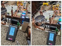
You also want the transformer far from the gear, as even this toroidy torodial which I believe is the very best shielded transformer avaliable, spews EMF (not RF or EF as measured here with grounding).
I addressed the EMF by using 0.5" thick aluminum plates in the top panel that are epxoy in with additional copper plates on the top. EMF doesn't matter about grounding but more so actual mass and distance. Remember, this transformer has electrical and magnetic shielding and in an epxoy housing that's further in a stainless steel enclosure.
I measured everything and based every decision based on effectiveness of a treatment strategy.
The free wire soup are just ground wires. The wires are long coming out of the copper tubes so I can run them up to the top layer easily and then cut as short as possible. They run through the 0.5" aluminum sheets and then copper sheet 0.08" copper plates (this is thick copper, must be cut with a cut off wheel) and into the various ucpure packs, which are further isolated individually with sorbothane and a full copper housing.
Further pics to come.
It is always finding the best balance of how you want to achieve the best results.
Long cables add impedance ... higher impedance adds sensitivity to external disturbances.
Fully incapsulating everything limits external disturbances.
It depends on the electronics if the higher impedance (with low distortion) or a low impedance (with a little higher distortion) works best.
Keeping the transformer away is a good thing but the noisy electronics (RPi) and clean electronics (reclocker / output / DAC) can be close to each other with a screening barrier like an aluminium plate.
I prefer to keep it short ... the signal cables and power supply cables at the local volage regulation / stabilisation
See also my response #10.088 at page 555 where I use a divider to protect the DAC board to the computer board.
Last edited:
@Oystein I can assure you a typical aluminum plate alone isn't enough. I have measured it.
Like I said, my toroidy transformer alone is already far better shielded than any other transformer I am aware of. I used 2 12" * 12" 0.5" thick aluminum sheets (my top layer WITHOUT any boards, power supplies ect weighs 40lbs alone.)
I still measure 400 mG for EMF at the toroid (which has internal electric and magnetic shields and a stainless steel shield) and then 5" away still 34 mG with the above plates and a copper plate for EMF.
For EMI and RF your better using copper plates and grounding them. EMF is better with thicker plates that are only economical in aluminum and it doesn't need to be grounded as it has no effect on EMF. For EMI and RF you must ground, otherwise you add EMI and RF. If you don't ground the aluminum, you must add a layer of copper that is grounded, otherwise the aluminum will increase the RF and EMI noise, while reducing the EMF. I am talking about 0.08" copper plates which are not cheap... They do not do anything for EMF vs a 0.5" aluminum plate. The aluminum plates even that thick are far inferior for EMI and RF. I have about $250 in copper plating, $100 in aluminum plating, and $200 in sorbothane in my build.
Rpi is a large source of EMI and RF, not EMF. You are far better here using copper plates that are grounded. The above pictures show the emi and rf reduction with the rpi, even without itself being incapsualted by copper (yet) by simply grounding and isolating everything else around it.
Last edited:
Aluminium and copper is not suitable to magnetic fields as generated by a transformer.
The reason is aluminium and copper are not magnetic .. for shielding transformers use steel or iron as these have magnetic properties.
For high frequency (radiated / RFI) noise aluminium and copper are fine.
The reason is aluminium and copper are not magnetic .. for shielding transformers use steel or iron as these have magnetic properties.
For high frequency (radiated / RFI) noise aluminium and copper are fine.
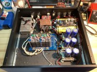
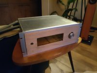
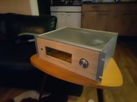
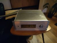
Work in progress, aluminum case and a wooden front.
large button for a Rotary encoder, left on/off and a 7.9 inch touchscreen.
mostly ian Canada electronica still has to be added.
still plenty to do.
large button for a Rotary encoder, left on/off and a 7.9 inch touchscreen.
mostly ian Canada electronica still has to be added.
still plenty to do.
Attachments
Correct, but ferrous material is not good around sensitive electronics and you can get the same effect with thick non ferrous material. The transformer itself already has stainless steel which is non ferrous but good for EMF and it's most definitely not enough.Aluminium and copper is not suitable to magnetic fields as generated by a transformer.
The reason is aluminium and copper are not magnetic .. for shielding transformers use steel or iron as these have magnetic properties.
For high frequency (radiated / RFI) noise aluminium and copper are fine.
The basic transformer almost everyone uses is spewing insane amounts of emf
- Home
- Source & Line
- Digital Line Level
- Asynchronous I2S FIFO project, an ultimate weapon to fight the jitter