Ok...the fifo is now 2 weeks active, so burning in should be complete.
I got from Ed the 44.x and 49.x version of the Crystek 957 with adapter boards ( thanks again, Ed!!!!).
Here are my Listening impressions:
With 22/24 Crystek 957:
Very warm sound overall. Colorful, rich mids. You follow the music easily. Very robust representation. Perfect ? Well...even though it improved a lot, no complaints on dynamics or 3d anymore, it still is a bit hazy, like if you have a tin-foil cap in the signal path than a mundorf silber supreme or better.
With the 44.x/49.x:
Did i complain about lack of transaprency ? Forget anything I said. Unbelievable fast and transparent. It lacks now the warm character a bit(still only fed by Placid hd shunt), but unbelievable resultion (and I have many Hd recordings). Like a highend Mundorf silver cap. Maybe not yet like a duelund with the color richness, but this could as well come from somewhere else in the chain, will figure it out. Clearly we are entering a new level and now I need to figure out other sources of errors made...
The crysteks are running currently without any decoupling caps...any opions on what would be the best ? smd parts like recommended by ian or mkp 1837 or micas ? hf chokes like tent suggests ? Oscons locally addionally ?
My bet is that the output jitter is dominated by the clocking flip-flops... It would be interesting to do the test with the Crystek. Likely Ian already did that
I have yet to see any datasheet having jitter values for flip flops which sort of indicates that jitter is not an important parameter for flip flops...
All flip flops add jitter.
The fun is that running on 3.3 volt may give 40% less added jitter, but the jitter spectrum are different from when running on 5 volt, and the slew rate are lower when running on 3.3 volt.
I do not know yet what the most important parameters are..
There are more than two ways to determine that - but listening and measurement are the obvious ones..
Sorry for interrupting the thread.
I want to use external power for each FiFO block kit, so with DualXO Clock I will remove L11 and with SPDIF I will remove j10 cable . It is right ? .
Thanks you .
For spdif board, yes, you need remove L1 if you run it from independent power supply.
But for dual xo clock board, you have to keep L11 if work with isolator board.
Ian
does anyone have the schematic link to Ian's 3.3v regulator.
got my mouser order with the ldo and I'd like to start soldering it.
thanks in advance.
The link is in the wiki
")
I created the wiki about a month ago for exactly this reason, to help people dig up the info buried in the long thread - let me know if you think there is things that could be done better in the wiki and I will try to add/change it to make it more usable for everyone. Also remember the wiki is publicly editable I believe so if anyone has something they would like to add, feel free to contribute
Wiki - diyAudio
Last edited:
Si570 Clock Board GB version V3.5(6) – Jitter measurement result
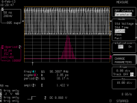
Yesterday, I received a finished GB version V3.5 Si570 clock board sample from my SMTA supplier to confirm. The first thing I did was measuring the real jitter performance. I think this part is what you are interested in the most.
Here is what got:
Period jitter RMS: 3.85 ps
Period jitter peak-to-peak: +-12ps
Jitter distribution: Gaussian
Frequency: 98.3097MHz
N = 10,000 cycles
Sampling at 8GS/s
Please see the attached jitter histogram plot for details
Please note, my oscilloscope comes with 2ps RMS jitter floor. If we take other factors into account, such as testing environment and calibration, the total jitter floor could be even bigger. So, if we exclude those numbers, the actual testing result we can figure out is not bad, very close to the period jitter specification from the official datasheet.
Again, measuring jitter in time domain is not the best way to evaluate a clock. Because we can see jitter from statistics only, but the spectrum. The best way is measuring it in frequency domain by a phase noise analyzer.
However, if we get testing results compared, it still tells a lot of secret. Please find the jitter testing result of the generic XO I posted weeks ago, you can see what is the difference in between.
Ian
Attachments
Thanks Ian, I think that looks great and seems devoid of the spurious noise some expect from such a device.... where is it guys? most seem to forget, or do not know that the clock is generated by an internal crystal.
for a speed of 98MHz I think this is very good, even if we do not consider the additional advantages of this multiple frequency clock. we can set it to be running at the ideal/preferred FS multiple for each sample-rate.
for a speed of 98MHz I think this is very good, even if we do not consider the additional advantages of this multiple frequency clock. we can set it to be running at the ideal/preferred FS multiple for each sample-rate.
Looks like a good result, even if Ian is right when saying the phase noise should be the best measurement.
BTW, the measurement should be done at 11.2896MHz, to directly compare to the generic XO measurement, and theorically (I repeat theorically) the noise in frequency domain should be better an so I expect improvement in time domain also.
I assume there is no period jitter measurement of the generic XO (stand-alone, not in the clock board), that could be very useful for to understand where the jitter come from.
BTW, the measurement should be done at 11.2896MHz, to directly compare to the generic XO measurement, and theorically (I repeat theorically) the noise in frequency domain should be better an so I expect improvement in time domain also.
Is there any post with the generic XO jitter measurement?
If yes, its jitter is around 6ps or lower?
I assume there is no period jitter measurement of the generic XO (stand-alone, not in the clock board), that could be very useful for to understand where the jitter come from.
Ian, those number look impressive. I did install yesterday the 45.X and 49.X Crystecs to the dual XO and the sound did improve a lot over the standard Xtals.
Next step is to feed the Buffalo with the clock signal from the dual XO with Crystecs.
Question for me is now if the SIC board would be a better choice or if the difference would be rather marginal ...
Next step is to feed the Buffalo with the clock signal from the dual XO with Crystecs.
Question for me is now if the SIC board would be a better choice or if the difference would be rather marginal ...
It's a great measurement result!
Would you reply to my primitive questions?
Please feel free to ignore those. I know very well that you are too busy.
1. In an example datasheet of oscillator devices, like this,
7311S-DF-255R(Fixed Communication)/Simple Packaged Crystal Oscillator (SPXO)/NDK
here we find such a description;
> Phase jitter (RMS) Max. 1 ps(12kHz to 20MHz)
Does your measurement give the frequency range condition as well?
The reason why I ask this is that I want to apply an apple-to-apple comparison.
2. Does the "N = 10,000 cycles" mean that your histogram and statistical calculation results are based on 10,000 sample pulses?
How many raw sampling points of which sampling frequency are used for the internal calculation in your LeCroy digital oscilloscope?
3. When we look at phase noise measurement charts, dBc/Hz values within 1-100 Hz range show big differences in general. Is your jitter histogram equivalent or does it cover the same frequency range?
Frequency: 98.3097MHz
N = 10,000 cycles
Sampling at 8GS/s
Would you reply to my primitive questions?
Please feel free to ignore those. I know very well that you are too busy.
1. In an example datasheet of oscillator devices, like this,
7311S-DF-255R(Fixed Communication)/Simple Packaged Crystal Oscillator (SPXO)/NDK
here we find such a description;
> Phase jitter (RMS) Max. 1 ps(12kHz to 20MHz)
Does your measurement give the frequency range condition as well?
The reason why I ask this is that I want to apply an apple-to-apple comparison.
2. Does the "N = 10,000 cycles" mean that your histogram and statistical calculation results are based on 10,000 sample pulses?
How many raw sampling points of which sampling frequency are used for the internal calculation in your LeCroy digital oscilloscope?
3. When we look at phase noise measurement charts, dBc/Hz values within 1-100 Hz range show big differences in general. Is your jitter histogram equivalent or does it cover the same frequency range?
no, Ian measures period jitter not phase.
Hi, Nazar_lv,
Thank you very much for your advice.
Would you tell me the difference between a period jitter and a phase jitter in spite of the same unit [ps RMS] if you have enough time or you know a good web pages that explain the difference in plain words?
Bunpei
Hi, Nazar_lv,
Thank you very much for your advice.
Would you tell me the difference between a period jitter and a phase jitter in spite of the same unit [ps RMS] if you have enough time or you know a good web pages that explain the difference in plain words?
Bunpei
Bunpei, you may review this: Jitter Specification: a Summary H i F i D U I N O
(I don't claim this is definitive, just based on my limited best understanding)I think phase jitter RMS = 10 x period jitter pp, but pp needs to measured for a larger sample according to industry standards...
Correction: 10,000 is industry standard...
So phase noise jitter RMS=2.4psec (pp being +/-12 or 24)
Last edited:
Hi Bunpei, sorry my time is very limited
http://www.diyaudio.com/forums/digi...timate-weapon-fight-jitter-9.html#post2689759
http://www.diyaudio.com/forums/digi...timate-weapon-fight-jitter-9.html#post2689759
Hi, glt & Nazar_lv,
Thank you very much for your help!
I should have read glt's comprehensive explanation page before I posted my previous question on the difference of "Phase Jitter" and "Period Jitter".
Now I think I understand well that a "Phase Jitter [RMS ps]" value is quite different from a "Period Jitter [RMS ps]" value and those two kind of values can't be compared directly.
In order to have a better understanding of the range coverage gap between "Phase Noise Graph" and "Period Jitter Histogram", I made a table as shown below.
The notation "d" is a deviation in a frequency domain and "Period" and "Period Jitter" are representation in a time domain.
_d[Hz]____d[ppm]_Freq[MHz]__Period[ps]__Period Jitter[ps]
-115900 -1179.00 98.188100 10184.533564 12.007522
_-37200 _-378.42 98.266800 10176.376966 +3.850924
_-10000 _-101.73 98.294000 10173.560950 +1.034908
__-1000 __-10.17 98.303000 10172.629523 +0.103481
___-100 ___-1.02 98.303900 10172.536390 +0.010348
____-10 ___-0.10 98.303990 10172.527076 +0.001035
_____-1 ___-0.01 98.303999 10172.526145 +0.000103
______0 ____0.00 98.304000 10172.526042 _0.000000
_____+1 ___+0.01 98.304001 10172.525938 -0.000103
____+10 ___+0.10 98.304010 10172.525007 -0.001035
___+100 ___+1.02 98.304100 10172.515694 -0.010348
__+1000 __+10.17 98.305000 10172.422562 -0.103479
_+10000 _+101.73 98.314000 10171.491344 -1.034698
_+37200 _+378.42 98.341200 10168.678031 -3.848010
+116300 +1183.06 98.420300 10160.505505 -12.020536
I think that the phase jitter measurement of ps order covers quite a different range from the phase noise 1-100Hz range.
To glt,
> I think phase jitter RMS = 10 x period jitter pp
Is the following expression correct?
phase jitter RMS = 0.1 x period jitter pp
Bunpei
Hi, glt & Nazar_lv,...
To glt,
> I think phase jitter RMS = 10 x period jitter pp
Is the following expression correct?
phase jitter RMS = 0.1 x period jitter pp
Bunpei
Oops, Yes
Without knowing the composition of the jitter/phase noise you really cannot arbitrarily map one to the other.
Also cycle to cycle jitter, which is very relevant to moving data may not show any low frequency components. I have tried measuring jitter on an FM modulated signal (+/- 100 KHz on 10 MHz and got less than 25 pS of jitter.
For DAC/ADC clocking you really need to look at the spectrum from 100 Hz (AES or really 20 Hz) to the max bandpass of the system. Beyond really doesn't matter much. The best way of course is in the audio output since that is what really matters.
For the TDA1541 fans...
I posted this over in Oliver's (dvb-projekt) DAC forum.
http://www.diyaudio.com/forums/group-buys/167414-reference-tda1541a-dac-i2s-bus-architecture-92.html
Ian...this is truly a game changer. Thanks.
I posted this over in Oliver's (dvb-projekt) DAC forum.
http://www.diyaudio.com/forums/group-buys/167414-reference-tda1541a-dac-i2s-bus-architecture-92.html
Ian...this is truly a game changer. Thanks.
I just started my BIIIse together with the Asynchronous I2S FIFO and a dual Clock board.
When I try 192kHz Music and with the MLCK instead of the BIII onboard 100MHz oscillator the BIII don't get a locked signal. I still havn't changed any of the oscillators included in the dual Clock board kit. (with 44.1kHz Music it works great).
It works perfect it I disconnect MLCK and uses the BIII Clock and only the I2S signal from the dual Clock board.
What could be the problem?
Also do anyone have recommendations on what Clocks to use for best performance out from the dual Clock board?
Thanks
Kenneth
- Home
- Source & Line
- Digital Line Level
- Asynchronous I2S FIFO project, an ultimate weapon to fight the jitter