The SCK will be 64*Fs. You can't use input bck, because the input bck if you are running the fifo belongs to a different clock domain.
Ian
So how must be the connection from the Si570 Clock to the TDA1541A?
As i read in the thread, the guys connected the TDA1541A direct to the FIFO. I think it must be like this:
FIFO------TDA1541A
SCK ---> BCK
WS ----> FS
SD ----> DATA

Cheers,
Oliver
So how must be the connection from the Si570 Clock to the TDA1541A?
In your case the Si570 is a drop in replacement for the Dual XO board, connections are the same just with the programmable MCLK frequency allowing you some flexibility.
On a separate note I had a glance down the FIFO GB interest list and there is an alarming number of people looking at 2 x Si570. Either a) more people than I expected either have two FIFOs OR b) more people than I expected have missunderstood and think that they need dual Si570 boards for one FIFO. Which is it? I don't know how to work that out.
Cheers,
Chris
Last edited:
In your case the Si570 is a drop in replacement for the Dual XO board, connections are the same just with the programmable MCLK frequency allowing you some flexibility.
I understand that, but Ian said that i couldn´t connect the SCK output from the FIFO to the BCK input of the TDA1541A.
That would mean that nobody could use the TDA1541A direct to the FIFO, because of the different clock domain, correct?

Oliver
I understand that, but Ian said that i couldn´t connect the SCK output from the FIFO to the BCK input of the TDA1541A.
That would mean that nobody could use the TDA1541A direct to the FIFO, because of the different clock domain, correct?
Oliver
I think there was some confusion, same as qusp misunderstood your post that Ian was replying to. The term direct I think they both took to mean direct from your i2s source, before the fifo.
What Ian meant here:
The SCK will be 64*Fs. You can't use input bck, because the input bck if you are running the fifo belongs to a different clock domain.
Ian
Is that the 'input bck' is the bck from your source (at the input to the fifo). Ian was stating the obvious that the bck must be the bck from the output of the fifo xo board (single xo or dual xo or si570).
Cheers,
Chris
Just for my understanding... If i use this combination:
Input with 192kHz --> FIFO --> Si570 clock --> TDA1541A NOS
what is the SCK output freq. (BCK input)? Could i use it direct, or must i use any logic converter?
Cheers,
Oliver
That´s what i mean. The TDA1541A limit for BCK (SCK - FIFO out) is 6.4 MHz.
If FIFO´s SCK = 64*FS than we have:
44.1 KHz --> 2.8224 MHz
48 KHz --> 3.720 MHz
88.2 KHz --> 5.6448 MHz
96 KHz --> 6.144 MHz
176.4 KHz --> 11.2896 MHz
196 KHz --> 12.544 MHz
If this above is correct, i couldn´t use the 176.4 and 196 KHz sampling rates.
So how must be the connection from the Si570 Clock to the TDA1541A?
As i read in the thread, the guys connected the TDA1541A direct to the FIFO. I think it must be like this:
FIFO------TDA1541A
SCK ---> BCK
WS ----> FS
SD ----> DATA
Cheers,
Oliver
I think there was some confusion, same as qusp misunderstood your post that Ian was replying to. The term direct I think they both took to mean direct from your i2s source, before the fifo.
What Ian meant here:
Is that the 'input bck' is the bck from your source (at the input to the fifo). Ian was stating the obvious that the bck must be the bck from the output of the fifo xo board (single xo or dual xo or si570).
Cheers,
Chris
We have really some misunderstandings, yes
Again, this is the connection i would like to do and all my questions above goes to this:
Wave I/O ---------> FIFO ----------> Red Baron DAC
BC ----------------> SCK -----------> BCK
LR ----------------> WS ------------> FS
DT ----------------> SD ------------> DATA
Cheers,
Oliver
It was about the max. usable sampling rate!
The TDA1541A limit for BCK (SCK - FIFO out) is 6.4 MHz.
If FIFO´s SCK = 64*FS than we have:
44.1 KHz --> 2.8224 MHz
48 KHz --> 3.720 MHz
88.2 KHz --> 5.6448 MHz
96 KHz --> 6.144 MHz
176.4 KHz --> 11.2896 MHz
196 KHz --> 12.544 MHz
If this above is correct, i couldn´t use the 176.4 and 196 KHz sampling rates.
Hi Ian
would you confirm that the DualXOboard can operate with 90.3168 MHz and 98.304 MHz XO?
Waiting for the Si570 clock board, I would like to try the following XO:
FXO-HC736-98.304 Fox Electronics | FXO-HC736-98.304-ND | DigiKey
Thanks
hirez69
would you confirm that the DualXOboard can operate with 90.3168 MHz and 98.304 MHz XO?
Waiting for the Si570 clock board, I would like to try the following XO:
FXO-HC736-98.304 Fox Electronics | FXO-HC736-98.304-ND | DigiKey
Thanks
hirez69
Last edited:
Ok, regarding the "time delay" issue we were talking about earlier. I thought of a possible solution (if it does work).
If i run all inputs (which is not sensitive to delay) straight into the FIFO, through a TP OTTO-II, then into the dual XO-board. Then i the source which is sensitive of delay into the secondary input of the OTTO-II (So that it would bypass the FIFO, which where the delay is) This would work, right? if i does - do i need to isolate the i2s signal before going into the dual XO-board?
If i run all inputs (which is not sensitive to delay) straight into the FIFO, through a TP OTTO-II, then into the dual XO-board. Then i the source which is sensitive of delay into the secondary input of the OTTO-II (So that it would bypass the FIFO, which where the delay is) This would work, right? if i does - do i need to isolate the i2s signal before going into the dual XO-board?
It was about the max. usable sampling rate!
This is a valid question/issue. I feel like I've been beating a dead horse in both threads but a true high class transport needs a 16 bit I2S, ie 32fs, the original standard I2S, not the hack standard phillips came up with for 24-32 bit I2s.
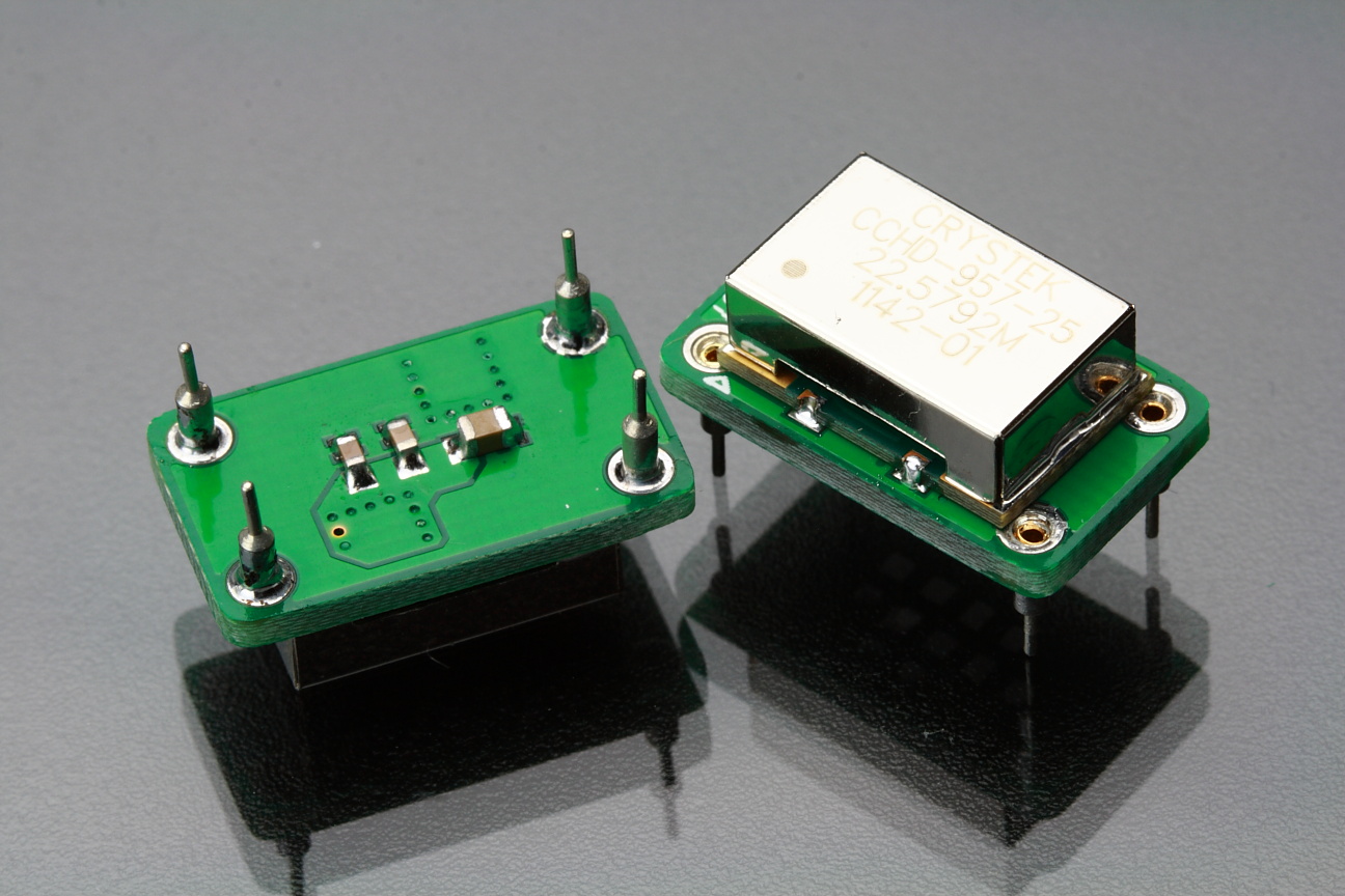
Got some Crystek CCHD-957s. Now i am probably a bit stupid but how does one solder these to Ian's boards without shorting the output pins. Ian's picture does not make it any clearer.
http://www.diyaudio.com/forums/atta...te-weapon-fight-jitter-cchd957withadapter.jpg
http://www.diyaudio.com/forums/atta...te-weapon-fight-jitter-cchd957withadapter.jpg
Last edited:
Hi Ian
would you confirm that the DualXOboard can operate with 90.3168 MHz and 98.304 MHz XO?
Waiting for the Si570 clock board, I would like to try the following XO:
FXO-HC736-98.304 Fox Electronics | FXO-HC736-98.304-ND | DigiKey
Thanks
hirez69
That clock will not give you any "hirez" results
- I bet Ians generic clocks are better or at least s good./
Got some Crystek CCHD-957s. Now i am probably a bit stupid but how does one solder these to Ian's boards without shorting the output pins. Ian's picture does not make it any clearer.
http://www.diyaudio.com/forums/atta...te-weapon-fight-jitter-cchd957withadapter.jpg
there is no copper on the corners of the clock underside, just center it as best you can
RollE2k, I'm having trouble following you, but its clearly not going to work. the dual XO bopard doesnt just work as a standalone reclocker for any signal you send to it.
Ok, that was a bummer then. Not even if you isolate the i2s before you send it to the XO-board? you have to run through the fifo?
the dual XO board doesnt just work as a standalone reclocker for any signal you send to it.
rephrasing the question doesnt change the answer =)
But how does the XO-board work then, if it's not only isolated i2s. I know the FIFO buffers the signal and sends to the XO-board, but what difference does the FIFO board have except that it buffers, that makes it impossible to send a isolated i2s into the XO?
I understand that you say it don't work - but my question now is rather why it doesn't work.
I understand that you say it don't work - but my question now is rather why it doesn't work.
because the clock board is controlled by the fifo main board and its input
its possible you could send it some 48khz audio directly before switching to fool it into staying on 48khz then send it movie data. possible, Ian will have to answer that. but honestly thinking up some mechanical system that may be kludged to work in theory and making something work in reality could easily be very different.
its possible you could send it some 48khz audio directly before switching to fool it into staying on 48khz then send it movie data. possible, Ian will have to answer that. but honestly thinking up some mechanical system that may be kludged to work in theory and making something work in reality could easily be very different.
Last edited:
That clock will not give you any "hirez" results
/
I agree with you: that clock doesn't show "pyrotechnic" performance
, but I don't see many alternatives for those frequencies, Ian's generic clocks included.
For "hirez" results we need Si570 board.
- Home
- Source & Line
- Digital Line Level
- Asynchronous I2S FIFO project, an ultimate weapon to fight the jitter