Hi TheShaman,
Since you're bringing this up, do you have a source for this type of schematics that everyone here interested in a battery setup could benefit from?
It would be interesting to find a good charging circuit that does all this. I have searched myself but never really found anything worth trying. Maybe I should be doing more digging but with all the projects I have running, I have had much less time. So if you know, please do share your knowledge!
Ciao!
Do
x2
and if so, i suggest we GB some of the new improved A123 ANR26650M1B; i have a direct and legit source from distributor for these, not grey market or fake and also their prismatic cells the AMP20M1HD-A, which would possibly be more suitable here, as they will last a very long time indeed driving a dac. not cheap those ones though at ~100usd each. but 2 of them would last an eternity here. 3.3v nominal 19.6Ah/65Wh and capable of putting out 1.2KW (up to 1.5KW for 10second pulses) hehe. i've been thinking of putting together a power source with 5-6 of these to run my whole rig sans power amps from. these still have 90% capacity after 3000 cycles
Technically, the clock should originate at the DAC, so no reclock or alignment should be necessary. You simply need to bring the clock to the Xmos chip without destroying it.Thats why you synch reclock (align) after isolation directly in front of the DAC, what ever happens on the digital side is a mute point if this is done well. The issue is you must use the same clock to drive the Xmos chip.
x2
and if so, i suggest we GB some of the new improved A123 ANR26650M1B; i have a direct and legit source from distributor for these, not grey market or fake and also their prismatic cells the AMP20M1HD-A, which would possibly be more suitable here, as they will last a very long time indeed driving a dac. not cheap those ones though at ~100usd each. but 2 of them would last an eternity here. 3.3v nominal 19.6Ah/65Wh and capable of putting out 1.2KW (up to 1.5KW for 10second pulses) hehe. i've been thinking of putting together a power source with 5-6 of these to run my whole rig sans power amps from. these still have 90% capacity after 3000 cycles
It leaves you enough headroom to run your AC on battery!

Jokes aside, I would be interested to power my xmos and DAC with battery. If we can find a really good charging circuit and use those batteries, I would be curious to know the price of this whole thing. I would be worth it I'm pretty sure!
Neat battery BTW... All round, very "sexy"
Do
Technically, the clock should originate at the DAC, so no reclock or alignment should be necessary. You simply need to bring the clock to the Xmos chip without destroying it.
Well the clock would be at the DAC chip, but you align the critical input(s) to the DAC with it. You can't just pump a 20+ mhz clock into a dac chip and expect it to do the synchrous alignment (maybe the ESS's can, don't know). It also depends on how the oversampling filter and dac combo works as to which dac inputs you would align . I agree the challenge is getting the clock back to the Xmos. I think we are saying the same thing?
@ TheShaman: as i see it there was no useable solution in that thread. well nothing i dont already have beat for my portable dac project using the ltc2935 and an external fast charger/balancer, i could use one of my spare pcbs but populated in a different manner and pirate the low battery shutdown signal to switch a relay either directly, or by biasing a transistor on. i'd be more inclined to have 2 batteries and the signal switches over to the other one and connects to the charge input, but maybe turn the charger on manually, because my charger pwns anything resembling diy
Last edited:
@ because my charger pwns anything resembling diy
Yes lithium battery charging isn't a diy job compared to the nice $100-$200 units. Its not as easy as it looks on the surface, you want the charger at the correct rate and ramps, with no trickling.
JMHO, but removeable bateries that you alternate, keep the charger away from the audio stuff. Get them setup with a plug-in. Don't use a socket that you can put them in backwards
I've had great long term luck with the fake A123 batteries, my guess is they all come out of the same factory. I've been alternating fake with real for over a year now with no difference.
@TheShaman: Nice position. What I meant, however, is whether a mathematician is a failed philosopher or the philosopher a failed engineer
Not sure. I do know that someone who goes deep into mathematics is bound to become a philosopher sooner or later (which is a nice way to say he/she'll go wacko
)!@ TheShaman: as i see it there was no useable solution in that thread. well nothing i dont already have beat for my portable dac project using the ltc2935 and an external fast charger/balancer, i could use one of my spare pcbs but populated in a different manner and pirate the low battery shutdown signal to switch a relay either directly, or by biasing a transistor on. i'd be more inclined to have 2 batteries and the signal switches over to the other one and connects to the charge input, but maybe turn the charger on manually, because my charger pwns anything resembling diy
Yes, unfortunately the bulk of communication (or information leeching
) must have been via PMs etc.With enough digging I'm sure we'll find a way.
I bought a smart (programmable etc.) charger as well and lost interest but perhaps I should restart my research. It'd be nice to have everything done automatically.
The only critical signal is the clock, so there is no need to align the other inputs. You can't align them if they're late, anyway, because that would require that your circuit know the future and provide those inputs before they arrive. The only alternative is to delay all signals by one clock cycle to make sure that they all arrive on time or early, but that's already happening inside the DAC anyway, so there's no real need to duplicate the process outside the chip.Well the clock would be at the DAC chip, but you align the critical input(s) to the DAC with it. You can't just pump a 20+ mhz clock into a dac chip and expect it to do the synchrous alignment (maybe the ESS's can, don't know). It also depends on how the oversampling filter and dac combo works as to which dac inputs you would align . I agree the challenge is getting the clock back to the Xmos. I think we are saying the same thing?
However, I believe there are some chips which only reference the master bit clock, while other chips reference both the bit clock and the word clock. If the latter, or any variation like that, then you really need to know which clock is the master and the consequences of other signal being late. However, the general principle with multi-signal serial links is that all the signals should be updated slightly ahead of the clock so that the clock can reliably read the other signals.
Maybe if you can point to a circuit example of how you would align the non-clock serial signals to the DAC clock then I would understand what you're trying to accomplish.
EDIT: Also, if there is another critical signal besides the clock that I'm missing, then please mention it. In my estimation, if you have a critical input that isn't aligned, then you've not successfully distributed the DAC master clock back to the driving circuits.
Last edited:
The only critical signal is the clock, so there is no need to align the other inputs. You can't align them if they're late, anyway, because that would require that your circuit know the future and provide those inputs before they arrive. The only alternative is to delay all signals by one clock cycle to make sure that they all arrive on time or early, but that's already happening inside the DAC anyway, so there's no real need to duplicate the process outside the chip.
However, I believe there are some chips which only reference the master bit clock, while other chips reference both the bit clock and the word clock. If the latter, or any variation like that, then you really need to know which clock is the master and the consequences of other signal being late. However, the general principle with multi-signal serial links is that all the signals should be updated slightly ahead of the clock so that the clock can reliably read the other signals.
Maybe if you can point to a circuit example of how you would align the non-clock serial signals to the DAC clock then I would understand what you're trying to accomplish.
EDIT: Also, if there is another critical signal besides the clock that I'm missing, then please mention it. In my estimation, if you have a critical input that isn't aligned, then you've not successfully distributed the DAC master clock back to the driving circuits.
I think we are saying the same things. Most of the DAC chips I play with never see the master clock, only the filter chip does. When you have a separate digital filter it does get more complicated because you want to do an alignment of the critical signal after the filter so as to remove the instrinsic jitter of the filter's output. As well as not feed jitter to the filter on its inputs because that jitter is encoded into the data..
Sidly, on the other site has a very good DIY CDP digital section that is a good example for a schematic and a good read if you are interested in alternatives to the modern all-in-one wonder chips.
But we're getting off topic For this thread the key indgrediant is somehow moving the masterclock(s) to the right. Diyers can figure out the rest.
Well, I would say that the DAC chip needs to see the master clock if you want minimal jitter. Not sure how the DAC can operate without a master clock.Most of the DAC chips I play with never see the master clock, only the filter chip does. When you have a separate digital filter it does get more complicated because you want to do an alignment of the critical signal after the filter so as to remove the instrinsic jitter of the filter's output. As well as not feed jitter to the filter on its inputs because that jitter is encoded into the data..
Meanwhile, a pure digital filter should be immune to jitter because it should process the data and not the clock. The only class of filter that reacts to jitter on its inputs would be ASRC, which should be avoided in a properly-clocked DAC system. I'm not saying there's no place for a digital filter, just that the problems you describe should be avoided rather than hacked around.
Well, I would say that the DAC chip needs to see the master clock if you want minimal jitter. Not sure how the DAC can operate without a master clock.
Meanwhile, a pure digital filter should be immune to jitter because it should process the data and not the clock. The only class of filter that reacts to jitter on its inputs would be ASRC, which should be avoided in a properly-clocked DAC system. I'm not saying there's no place for a digital filter, just that the problems you describe should be avoided rather than hacked around.
Not hacks, classic synchronous reclocking as used with Digital Filters and Multibit dac chips inside CDP's for the past 15 years. The key of course being able to share the masterclock with the Xmos chip.
Hey at least we agree ASRC should be avoided
I think we are confusing each other when referring to a DAC, sometimes meaning the complete unit and other times meaning the dac chip.
Forget about my experiements with the old chips, Probably the xmos isn't the best for those anyway. All they need is a single clock for rbcd typically
256xfs=11289.6 (instead of the 2 512fs clocks on the waveio.)
I am also slowly tinkering with a fairly modern chip the WM8741. Do you know if there will be truncation with the I2S format? Does the WaveIO output 32+32 word length I2S or is it the standard phillips 24+24 I2S? I know the WM8741 has a few dither modes but don't think it can dither past beyond the 24th bit. I think only the Sabre's, new AKM, and new BB can handle 32 bits without truncating?
Last edited:
Driver disecting
On another note.,
in the USB Audio Class Driver Control Panel., the Stream Formats are both grayed out, is it the same for everyone who is using this driver ?. Sure would be nice to see the Input and Output Stream Formats functioning.,
thanks for your taught s on this .
regards
reo
On another note.,
in the USB Audio Class Driver Control Panel., the Stream Formats are both grayed out, is it the same for everyone who is using this driver ?. Sure would be nice to see the Input and Output Stream Formats functioning.,
thanks for your taught s on this .
regards
reo
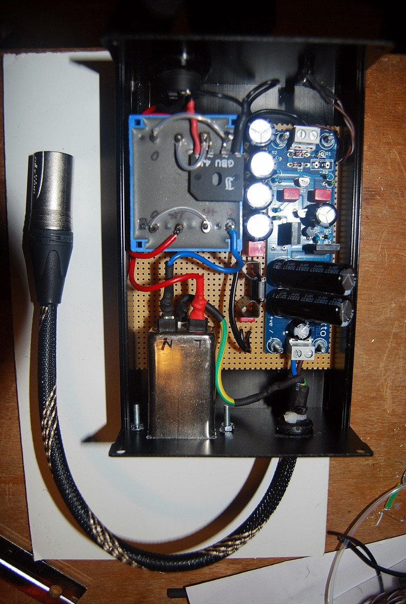
So, made a cheap box for trying the spdif transport capabilities of Waveio and connected to the (also very cheap) PSU with JLH Ripple Eater...
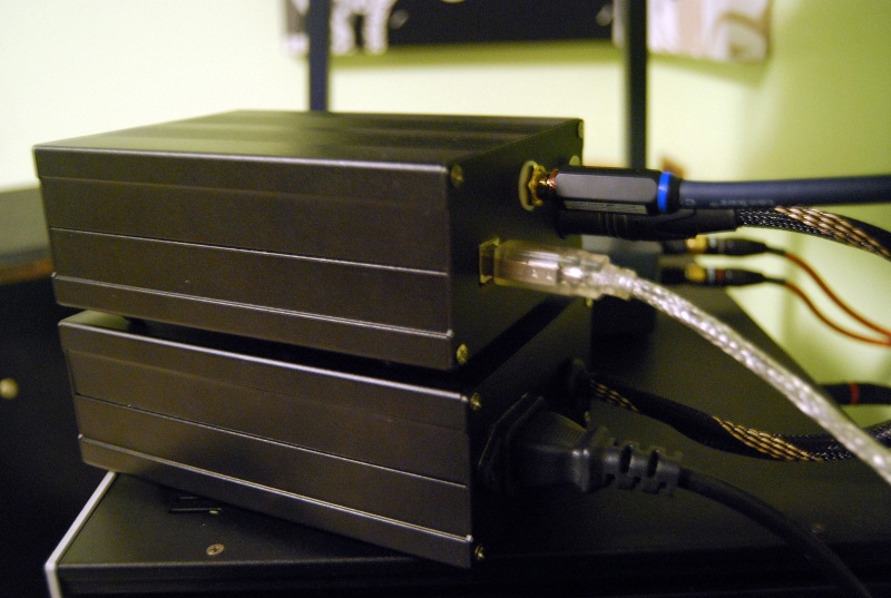
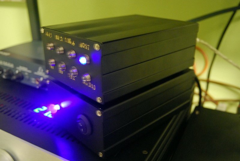
Tried with ASIO in my Audio-GD NFB-12 and worked flawlessly...
Brought my inexpensive dac another level, I must say...
If also a cheap DAC like that can have such an improvement, a Buffalo and I2S connection are coming next!
Thank you, Lucian!
Tried with ASIO in my Audio-GD NFB-12 and worked flawlessly...
Brought my inexpensive dac another level, I must say...
If also a cheap DAC like that can have such an improvement, a Buffalo and I2S connection are coming next!
Thank you, Lucian!
So, made a cheap box for trying the spdif transport capabilities of Waveio and connected to the (also very cheap) PSU with JLH Ripple Eater...
Tried with ASIO in my Audio-GD NFB-12 and worked flawlessly...
Brought my inexpensive dac another level, I must say...
If also a cheap DAC like that can have such an improvement, a Buffalo and I2S connection are coming next!
Thank you, Lucian!
I am surprised it helped the nfb-12, I have one but it measures high distortion (starts with -80dB 2H) stock. Was planning on adding an arudino along with the WaveIO with a new enclosure and better output stage. Glad this turned out good for you.
I am also slowly tinkering with a fairly modern chip the WM8741. Do you know if there will be truncation with the I2S format? Does the WaveIO output 32+32 word length I2S or is it the standard phillips 24+24 I2S? I know the WM8741 has a few dither modes but don't think it can dither past beyond the 24th bit. I think only the Sabre's, new AKM, and new BB can handle 32 bits without truncating?
If Lorien or someone who knows the answer could answer this question about waveio output being 24+24 or 32+32 I'd be interested also.
- Home
- Source & Line
- Digital Line Level
- XMOS-based Asynchronous USB to I2S interface