I put in a new pot, but the control signal is the original one, tapped from the 20-pol connector. As the display has some problems I might change the whole display and control. I have a Raspberry PI laying around. Just have to learn to program it...
What regulator(s) do you recommend? I noticed during the build that AVCC was a bit high 3.5V. So I had to adjust the ntd1 to 1.75V.
What regulator(s) do you recommend? I noticed during the build that AVCC was a bit high 3.5V. So I had to adjust the ntd1 to 1.75V.
I tapped the motor pot outputs from the CPU. So I can use the original remote control.
And I'm using SE output. So only caps on pos output. I did try Lundahl trafo to convert bal-SE and that sounded good as well. But the best was to use a 47k dummy load on the bal- output. I made the sound go from a bit dull and not so airy to shimmering and sparkling.
I want to thank opc and all the time, effort and excellent engineering that was put into this project.
Hi deerhunt,
I have one build of the same as well and using Arduino setup to control the DAC. I'm only using the balanced output ever since I got it. I will definitely try your mod to be able to use it on my SE amplifiers.
Thanks
Do
@reenberg
The 9018 and NTD1 is the best I've tried. A bit "dark" in tonal balance but when I compare to other output stages or dac it has better dynamics, ambience and deeper soundstage. It doesn't accentuate sibilants and is completely unaffected by volume setting, i.e. sounds wonderful at all volumes.
I tried IVY3, Legato4, tube o/p, Lundahl trafo and LCaudio Zapfilter.
@pinnocchio
That Arduino solution seems nice. Did you change to trident regs on your B2? I'm a bit curious if and how it improves sound quality.
Same boat
I run a V.4 NTD1 (Clarity CMR caps) with a B-IIIse, Sonore USB interface (isolated) and prefer it's sound to almost all other options. It has a live character, presence, and ability to do dynamic shading that is quite remarkable.
Lately I've been sending it only DSD2 oversampled in Audirvana (streaming over Ethernet), and that really sounds great.
@pinnocchio
That Arduino solution seems nice. Did you change to trident regs on your B2? I'm a bit curious if and how it improves sound quality.
Yes, I'm currently using Paul Hynes regs on the BII but AVCC Dual is still Trident. I wouldn't know how to compare them now since it's been too long but as I recall back when I did the changes, I didn't find it change anything but my memory could be faulty. All I know is it sounds really good. There was definitely a step up from onboard regs to Trident/Paul Hynes though. But again, what were the nuances, I cannot remember.
Do
Is there any info about using NTD1 with 9038, any modification needed ?
I am not sure what the specific change will be, but you will need to adjust to accommodate the higher (8x) current output.
The current increase from the 9018 to the 9038 is 4x, not 8x, right?
Unless I'm reading the data sheets wrong, the 9018 outputs ~4 mA per channel, x8 channels, for 32 mA total (16 mA per stereo side) and the 9038 outputs ~16 mA per channel, x8 channels, for 128 mA total (64 mA per stereo side).
Assuming the above is correct, I've outlined the changes you'd have to make to the NTD1 for it to work with the 9038 here: "The Wire" Official Boards for All Projects Available Here! BAL-BAL, SE-SE, LPUHP
The trade off for handling the extra current and maximizing low input impedance is less gain. In practically every scenario you'll need a gain stage after the NTD1 to get the output back up to levels necessary to drive a power amp. You can play with the resistor values and supply voltage to get a combination of gain, impedance, and dissipation you're happy with.
Owen mentioned that he's working on an "all in one" board that combines the NTD1 and BAL-BAL, but I'm not sure of the current status.
Last edited:
The current increase from the 9018 to the 9038 is 4x, not 8x, right?
Yes, 4x. Posting in haste at work ��
I am not sure what the specific change will be, but you will need to adjust to accommodate the higher (8x) current output.
That holds as true that BIIIsePro ES9028 is drop-in replacement for a BII/BIIIse? Tempting!
MOSFET matching results
Hello,
I've been slowly gathering the required bits and pieces to build the NTD1 and I've finally finished matching the mosfets.
I have the V4 PCB with all SMD components so the mosfets are those specified on the newer BOM: the FDB52N20. I only ordered 10 of them for now to test the matching process. I used the matching instructions Owen posted, with a lab power supply set at 45V and a signal generator at 1kHz. The D2Pak format of the mosfets was a little challenging to work with (tried to avoid soldering/desoldering each one while still having it on a heatsink).
The results show a smaller transconductance than what was measured for the FQA32N20, so I'm wondering if my measured values look ok?
Thanks
Attachments
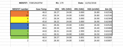
I just noticed that I didn't adjust the testing rig to account for the decrease in supply voltage from 45V to 38V for V4 of the NTD1.
Given that we want about 100mA of idle current, I would adjust VR1 to 18 VDC (Vds of 20V) and keep everything else in the rig the same for the measurements of Vgs and matching for Vds?
Given that we want about 100mA of idle current, I would adjust VR1 to 18 VDC (Vds of 20V) and keep everything else in the rig the same for the measurements of Vgs and matching for Vds?
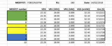
To follow up on my question, for anyone else that may be wondering the same thing, I can confirm that Vds should be 20V and the voltage should be adjusted to obtain 18V across R1 when matching mosfets for V4 of the NTD1. Those were the exact measures I got after finishing the NTD1 and measuring everything on the board.
These are the values I got with the appropriate settings for only 10 FDB52N20. I used # pairs 6-7 and 5-9 for my NTD1, so would have #1-2-3-8 that could be used for another V4 NTD1 if anyone needs them and doesn't feel like matching mosfets.
These are the values I got with the appropriate settings for only 10 FDB52N20. I used # pairs 6-7 and 5-9 for my NTD1, so would have #1-2-3-8 that could be used for another V4 NTD1 if anyone needs them and doesn't feel like matching mosfets.
Attachments
Didn't see an answer to Malefoda's question.
Is it possible to use the newer BIIIsePro ES9028 with the v3 version of the NTD1 as a drop in replacement for the BIIIse?
The output levels are the same, so it should drop right in.
- Home
- Source & Line
- Digital Line Level
- Build Thread - A New Take on the Classic Pass Labs D1 with an ESS Dac