I hope the CPLD on that white pcb accepts a 512x MCLK (22.579MHz) so that I can feed it by an up-to-date USB to I2S board, in my case that'll be a JLsounds board. Of course I tried this particular board also in simultaneous mode, including the inverting stage for balanced out. I never was happy with that solution as it has clicks and pops at every interruption of the data stream. Also, I do not want to use any mute circuitry, that's against my understanding of the positive features, a balanced circuitry has.
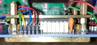
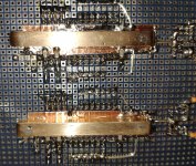
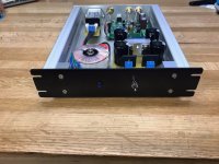
And yes, those are brass bars above the TDAs, complimented by a really solid brass bar underneath the chips. Heat transfer is so good, i was not able so solder the GND side of the MLCCs with my 80W+ soldering iron")
And yes, those are brass bars above the TDAs, complimented by a really solid brass bar underneath the chips. Heat transfer is so good, i was not able so solder the GND side of the MLCCs with my 80W+ soldering iron
Attachments
Recent DAC project
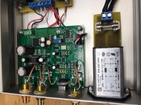
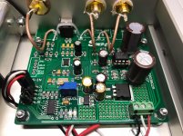
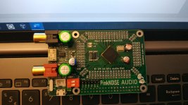
Here’s a recent project I built based on the ESS ES9038Q2M DAC chip on a Chinese module acquired through Ebay. This is a stand alone DAC in its simplest form with just one optical and one coaxial digital input and the analog output.
I have made a few minor mods to the module which include:
1) removed the on board connectors for the input, outputs, and power so I could use panel mount connectors instead. Left the optical input intact.
2) added the screw terminal for DC power connection
3) removed the volume control connector and replaced it with a multi-turn pot for level matching
4) replaced the output coupling capacitors with Elna Silmic series audio caps.
5) replaced the NJM5532 with an LT1057 (done after the photos)
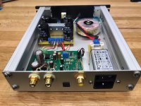
The power supply is just a simple +/- 15 VDC design built with 78/79 series regulators. The case was built from industrial scrap and aluminum panels recovered from an old Mac computer case.
PCM filter selection is done manually with jumpers. The ES9038Q2M has 7 available filter types, all of which don’t start to roll off until 20 KHz or higher. I tried them all and couldn’t hear any difference, so I saw no need for a more advanced selection method. I simply chose the linear phase slow roll off filter because it has the cleanest impulse response as indicated in the data sheet graphs.
I am very pleased with the sound, as it is clean, detailed and smooth. Separation and imaging are also very good. I’ve been listening for about 8 months to an identical module I put in another system, so I have had the chance to listen to a wide variety of recordings all of which sound great.
I don’t have the equipment to make any distortion measurements so I can’t provide any info in this area. Thanks.
Here’s a recent project I built based on the ESS ES9038Q2M DAC chip on a Chinese module acquired through Ebay. This is a stand alone DAC in its simplest form with just one optical and one coaxial digital input and the analog output.
I have made a few minor mods to the module which include:
1) removed the on board connectors for the input, outputs, and power so I could use panel mount connectors instead. Left the optical input intact.
2) added the screw terminal for DC power connection
3) removed the volume control connector and replaced it with a multi-turn pot for level matching
4) replaced the output coupling capacitors with Elna Silmic series audio caps.
5) replaced the NJM5532 with an LT1057 (done after the photos)
The power supply is just a simple +/- 15 VDC design built with 78/79 series regulators. The case was built from industrial scrap and aluminum panels recovered from an old Mac computer case.
PCM filter selection is done manually with jumpers. The ES9038Q2M has 7 available filter types, all of which don’t start to roll off until 20 KHz or higher. I tried them all and couldn’t hear any difference, so I saw no need for a more advanced selection method. I simply chose the linear phase slow roll off filter because it has the cleanest impulse response as indicated in the data sheet graphs.
I am very pleased with the sound, as it is clean, detailed and smooth. Separation and imaging are also very good. I’ve been listening for about 8 months to an identical module I put in another system, so I have had the chance to listen to a wide variety of recordings all of which sound great.
I don’t have the equipment to make any distortion measurements so I can’t provide any info in this area. Thanks.
Attachments
Thanks for sharing your experience with the Elna Silmic caps. I haven't tried anything else except the originals, which were Nichicon FW series which are "for audio use" according to their data sheet. Didn't really notice much difference with the Elna caps though. What brand/type of film caps did you end up using?
I know what you say, Mark, but I don't actually know why a like should imply a dislike. I like them both, R-2R and SD.
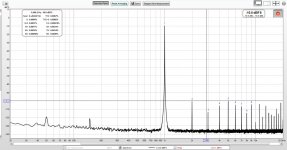
There is a huge improvment for the master version. Measuring THD, it is the same, about 0.006%, no matter what input SR is, from 44.1 kHz to 384 kHz. Only SN is lower for higher SRs. I used a dual 90.xxxx/98.xxxx MHz oscillator sample, left from an ES9018K2M project, so it was possible to generate 45/49 MHz bclk for 352/384 sample rates.
In the first, slave, version I used a 50MHz single freq. oscillator for CPLD and this is the reason why THD values varies quite a bit depending on the sample rate.
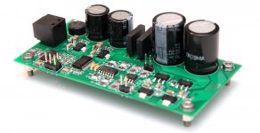
DIR9001+PCM1794A
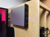
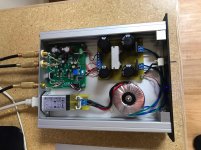
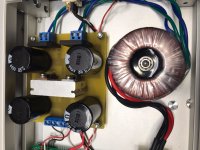
Optical S/PDIF input. Everything on one PCB, including the PSU. Just connect the transformer and thats it...
Now I just need to put it in a nice small enclosure.
I needed something to get the sound out of a new TV set. So I made that...
Optical S/PDIF input. Everything on one PCB, including the PSU. Just connect the transformer and thats it...
Now I just need to put it in a nice small enclosure.
I needed something to get the sound out of a new TV set. So I made that...
Attachments

Hi amigos,
I discovered a brand new unknown DAC, it is using the same chips as the Soncoz SGD1.
The Lead Dual 9038Q2M is amazing at its price, the inputs interface is crazy !!!
Check here, I wrote a short review VS the Gustard X16.
LEAF Dual 9038Q2M VS Gustard X16 pictures inside )
SPEC :
Audio input: Bluetooth / USB / LVDS / Optical / Coaxial
Audio output: Stereo RCA / XLR / Balanced headphone jack
BT CSR8675 supports ACC/SBC/APTX/APTX-LL/APTX-HD/LDAC
USB XMOS XU208
IIS that supports DSD64-DSD512 de 32 bits/384Khz,
USB that supports DSD64-DSD256 de 32 bits/384Khz
Opitcal that supports 192KHz y DOP DSD64
Coax PCM 44,1 K-192K/24bit.
RCA inputs 2V RMS
XLR inputs 2V RMS
Headphone amp output power: 1.5W/32Ω, 200mW/300Ω
Matched headphone impedance: 16-300Ω
Thanks for the write up. I ordered the Leaf because of all the interconnects, especially the balanced XLR output (and the low price, $203 cdn delivered). Looking forward to see how it compares to my old, but still capable PS Audio Digital Link iii. Curious to see how long it takes to arrive.
DAC8
Hello all, I want to share with you the result of my build called "DAC8". This is a DAC / Mediaplayer trough Logitech Media Server protocol implementation and decoding of MP3/AAC/FLAC and PCM. The DAC section is build with a quad PCM1704, DF1706 oversampling filter and a ADAU1701 DSP for room equation. The mediaplayer is a ESP32 for the wireless part and userinterface, and a sipeed MAIX module with dual core RISC V CPU running at 2x 500MHz for the decoding of mediafiles. The display is a DWIN module of 8,8 inch and 1920x480 resolution. The housing is my own development (lots of work ) and I built it in the same style as my last years build of the DIY Audio Honeybadger Amp.


The T7 Honeybadger AMP:


Hello all, I want to share with you the result of my build called "DAC8". This is a DAC / Mediaplayer trough Logitech Media Server protocol implementation and decoding of MP3/AAC/FLAC and PCM. The DAC section is build with a quad PCM1704, DF1706 oversampling filter and a ADAU1701 DSP for room equation. The mediaplayer is a ESP32 for the wireless part and userinterface, and a sipeed MAIX module with dual core RISC V CPU running at 2x 500MHz for the decoding of mediafiles. The display is a DWIN module of 8,8 inch and 1920x480 resolution. The housing is my own development (lots of work
) and I built it in the same style as my last years build of the DIY Audio Honeybadger Amp.
The T7 Honeybadger AMP:
Last edited:
- Home
- Source & Line
- Digital Line Level
- DAC gallery