My recent DIY R2R DAc for Raspberry Pi
Building Discrete R-2R DAC Hat - Part-1 - YouTube
Building Discrete R2R DAC Hat - Part 2 - YouTube
Building Discrete R-2R DAC Hat - Part-1 - YouTube
Building Discrete R2R DAC Hat - Part 2 - YouTube
Your designs look very professional, congratulations!
@audiophilediyer
Nice videos. I am already working to a similar project, still based on EPM240, F version (100 x 1 mm pitch balls). As I can calculate, they remain available around of 13 pins. So, since they are not enough to make a 4-bits thermometer, instead of 3-bits, I am thinking to make two of 5-bits offset trimming circuit, 10 more pins for both channels. I haven't make a decision yet if I will stay on RaspPI size PCB, or I should go to a little bigger one.
Anyway, I have seen your videos, twice, it was a real pleasure. "Home" made, but to another level.
Hi Thorp,
Thank you.
I have very little BGA experience for my DIY projects, it save space for smaller board though.
In fact , I had built many versions of discrete R2R in this few years , I still prefer hand picked resistors with segmented configuration.
A few of my previous signed-magnitude R2R DACs has very very low distortion , but strangely , it doesn't sound as good as segmented R2R. Maybe I'm missing something .When I compare my segmented R2R VS signed magnitude R2R, the signed-magnitude R2R sounds a little bit "artificial " then the segmented R2R .
Please share photos of your R2R DAC once you have already completed yours.
-audiophilediyer-
just my 2 cents, but should we not use the DAC gallery for DIY pictures and not direct advertisement ?
Please share photos of your R2R DAC once you have already completed yours.
-audiophilediyer-
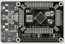
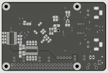
PCBs for first prototype are ready to be ordered.
Since I have no any experience with CPLD based DACs, it will be a simple SLAVE one, for learning purpose, but for the final design, it will be a MASTER version, I hope. (CPLD will send 45/49 MCLKs and BCLKs to RPi)
Attachments
PCBs for first prototype are ready to be ordered.
Since I have no any experience with CPLD based DACs, it will be a simple SLAVE one, for learning purpose, but for the final design, it will be a MASTER version, I hope. (CPLD will send 45/49 MCLKs and BCLKs to RPi)
Nice! looking forward to see further progress!
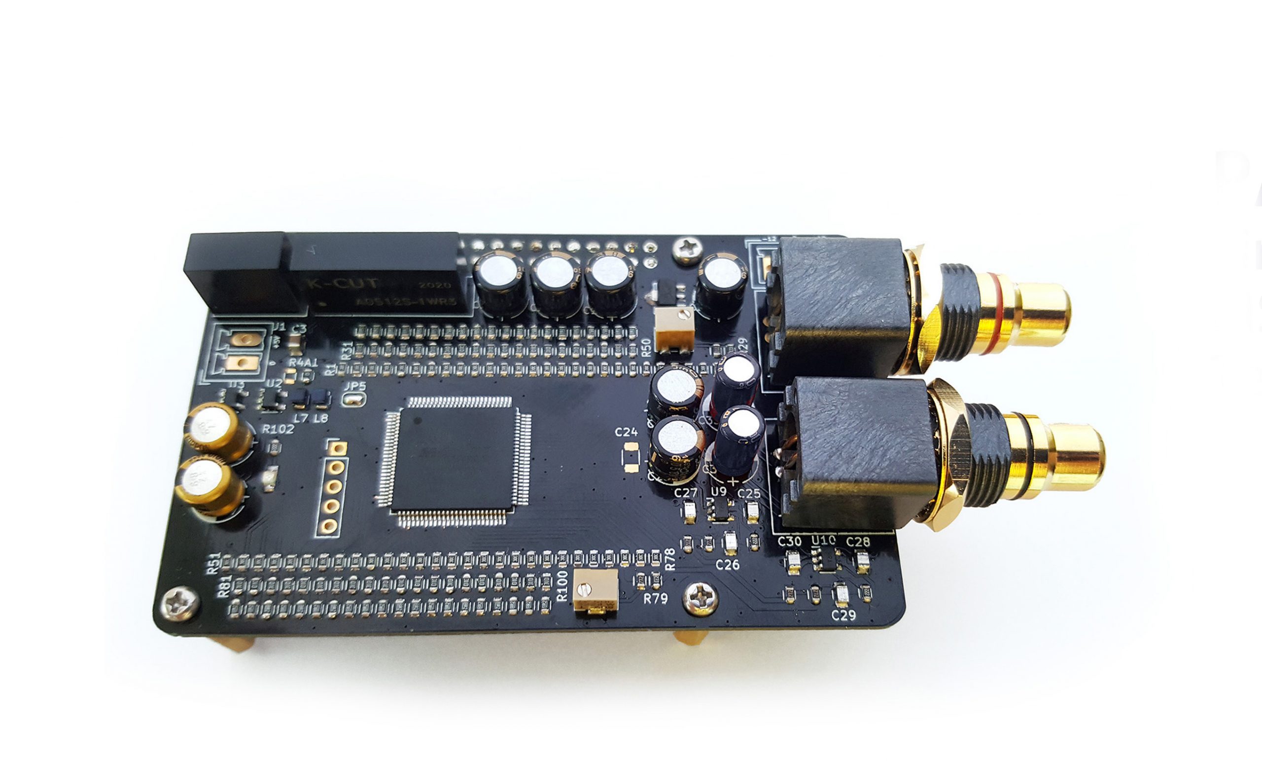
First test: it realy sounds amazing.
This is the DAC with the worst THD I've ever built, at least in theory. My newer RPi didn't arrived yet, but the old one is good enough for testing.")
On the PCB there is one technical issue: the low noise power supply for opamp is missing ADP7118, because I ordered the wrong package!!!, so you will see a short wire in that area. Opamp is low noise, low enough THD, ISL28291, but for the moment it is powered directly from main 5V power supply.
I am sorry for the video quality, it is a preview only.
For me, there are 3 premieres: first R-2R DAC, first CPLD project and first BGA package soldered.
MAX II APHITHEATER R-2R DAC for Raspberry Pi - YouTube
This is the DAC with the worst THD I've ever built, at least in theory. My newer RPi didn't arrived yet, but the old one is good enough for testing.
On the PCB there is one technical issue: the low noise power supply for opamp is missing ADP7118, because I ordered the wrong package!!!, so you will see a short wire in that area. Opamp is low noise, low enough THD, ISL28291, but for the moment it is powered directly from main 5V power supply.
I am sorry for the video quality, it is a preview only.
For me, there are 3 premieres: first R-2R DAC, first CPLD project and first BGA package soldered.
MAX II APHITHEATER R-2R DAC for Raspberry Pi - YouTube
Nice work. Next steps, reclocking the digital signals ?
Thank you. Yes, I have planed to make the master version (RPi slave) of this DAC. I will use the same PCB, with some modification for signal isolator.
It is funny, because I thought initially that I have to reverse it 180 degrees only, but after a ordered PCB, I realised that even if data pins are simetrical, VCC and GND pins of the IC are not!!!
Next-next step is FPGA based project, to deal also with DSD(dop) signals from RPi
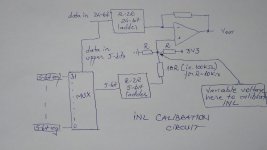
The board says 24 bit. Did you do a linearity test ?
Not yet. Actually both (left + right) 5-bit R-2R ladders for INL calibration are inactive at this moment. I will use variable voltage on opamp non-inverting input to deal with INL. See please the picture below.
Attachments
Thorp,
Interesting project. I don't know if its the best way to go in the end, but dacs of the type are are building can sometimes even sound a little more dynamic than the recording really is. On the other hand, SD dacs can sound bit flat in terms of perceived dynamics. There are ways to compensate both types of dacs for perceptually more natural sound. The question for me which type can produce a better overall sounding result with compensation/correction in place. Ultimately, I suspect a compensated SD dac will do better. Time will tell I guess.
Interesting project. I don't know if its the best way to go in the end, but dacs of the type are are building can sometimes even sound a little more dynamic than the recording really is. On the other hand, SD dacs can sound bit flat in terms of perceived dynamics. There are ways to compensate both types of dacs for perceptually more natural sound. The question for me which type can produce a better overall sounding result with compensation/correction in place. Ultimately, I suspect a compensated SD dac will do better. Time will tell I guess.
That's a good question because I am not aware of any peer reviewed published research on that subject.whats your reference?
Thorp, not sure if you have the equipment to do a linearity test up to 24 bits, but if you want I can run that for you on my Audio Precision equipment.
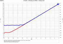
for example, below is the linearity of the DDDAC 1794 - as you will see it is almost impossible to reach true 24 bit linearity
This was actually a test I ran as some one mentioned the Vcom decoupling on the PCM1794 was not necessary. I proved him wrong as you can see ...
Of course R2R dacs with non-laser trimmed resistors for LSBs and wanting to do 24 bit is quit a challenge, so checking this is a MUST so you know if you reached your design goals
any way up to you !
Attachments
Thank you @dddac for your feedback.
Now I see your point: of course it is not a trully 24 bit dac! When I named that, I reffered to the "size" of R-2R ladder.
This is a learning project, actually my goal is to (start) learn about FPGAs & CPLDs. I don't even have a modern RPi (but it will arrive today, the courier just called me )
It is just a hobby and, yes, you are right, I don't have any expensive equipment, but I wish to!
On the other side, I am on your side: I also want to reach the best possible version of something I work to. Even if I believe that no one can hear any difference between "with 47uF" and "without 47uF", I still woluld do as you did! Perception can be subjective, but the numbers (math) don't lie, actually they are our common language.
Now I see your point: of course it is not a trully 24 bit dac! When I named that, I reffered to the "size" of R-2R ladder.
This is a learning project, actually my goal is to (start) learn about FPGAs & CPLDs. I don't even have a modern RPi (but it will arrive today, the courier just called me
)It is just a hobby and, yes, you are right, I don't have any expensive equipment, but I wish to!
On the other side, I am on your side: I also want to reach the best possible version of something I work to. Even if I believe that no one can hear any difference between "with 47uF" and "without 47uF", I still woluld do as you did! Perception can be subjective, but the numbers (math) don't lie, actually they are our common language.
Indeed Thorp, doing what you did is a great learning process and I am very interested in your results. My offer stands, if you at any point feel it would be nice to have a Linearity, THD, Noise, Frequency transfer - measurement - straight from digital source to analog output, let me know
Thank you. Yes, I have planed to make the master version (RPi slave) of this DAC. I will use the same PCB, with some modification for signal isolator.
It is funny, because I thought initially that I have to reverse it 180 degrees only, but after a ordered PCB, I realised that even if data pins are simetrical, VCC and GND pins of the IC are not!!!
Next-next step is FPGA based project, to deal also with DSD(dop) signals from RPi
Not yet. Actually both (left + right) 5-bit R-2R ladders for INL calibration are inactive at this moment. I will use variable voltage on opamp non-inverting input to deal with INL. See please the picture below.
It depends on the clock rate on the output side but FPGA/CPLD clocks may give you problems. A lot of the R2R dacs use a shift register, load serially, then use the clock against the SR to enable the pulse for output. That way all the pulses are better aligned. Looking at the traces on the PCB, they're of varying lengths too which may cause problems are higher rates.
Btw you can get digital potentiometers that can be programmed via SPI etc, if you have a calibration step manually then use a digital to fine tune where human fingers can't.
Love the DAC name btw
Last edited:
Hi, NickKUK, thank you for your feedback.
I agree, but unfortunately, it is hard to draw so many matched length wires on an RPi size PCB. Some FPGAs are already on the way: EP4CE22 in 16x16, 1 mm pitch balls - that means 17x17 mm sq. footprint, and EP4CE40 in 22x22 , 0.8 mm pitch balls - that means 19x19 mm sq. footprint. They are huge for such as small PCB size! More than that, I want to use them in combination with AK4137 - these ones already arrived -, so, it is hard to believe that I will be able to put all of them on the same RPi size PCB.
At least because of the isolators, some hi-q IC flip-flops are mandatory, I am still looking for them. Anyway, at this moment, this project is in my mind only.
I have finally managed today to compile my first functional kernel modules for Volumio! I've been working on this for a few weeks and I had during this time some moments when I wondered how Linux-based distributions actually work! But, I am happy now and I really believe that Linux is a fascinating world.
I agree, but unfortunately, it is hard to draw so many matched length wires on an RPi size PCB. Some FPGAs are already on the way: EP4CE22 in 16x16, 1 mm pitch balls - that means 17x17 mm sq. footprint, and EP4CE40 in 22x22 , 0.8 mm pitch balls - that means 19x19 mm sq. footprint. They are huge for such as small PCB size! More than that, I want to use them in combination with AK4137 - these ones already arrived -, so, it is hard to believe that I will be able to put all of them on the same RPi size PCB.
At least because of the isolators, some hi-q IC flip-flops are mandatory, I am still looking for them. Anyway, at this moment, this project is in my mind only.
I have finally managed today to compile my first functional kernel modules for Volumio!
I've been working on this for a few weeks and I had during this time some moments when I wondered how Linux-based distributions actually work! But, I am happy now and I really believe that Linux is a fascinating world.balanced TDA1541
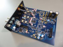
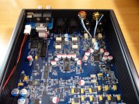
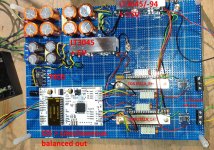
A straight-forward balanced TDA1541 testbed to confirm the AliXpress I2S to simultaneous board (the white pcb) really works.
It's not finished yet (who wonders?), the analog output stage is just a quick'n dirty OPA1656 active I/V followed by a cheap TPA6120 headphone amp.
I'll switching to a passive R tube amplified setup later.
On my try-out list are the Broskie "unbalancer" and the Tubeclinic 6N16B preamp.
Attachments
- Home
- Source & Line
- Digital Line Level
- DAC gallery