Drawing files for Pre-amp back panel
Hello,
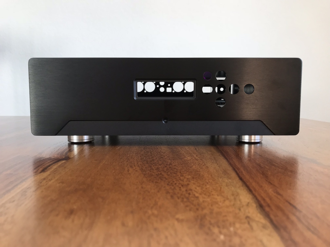
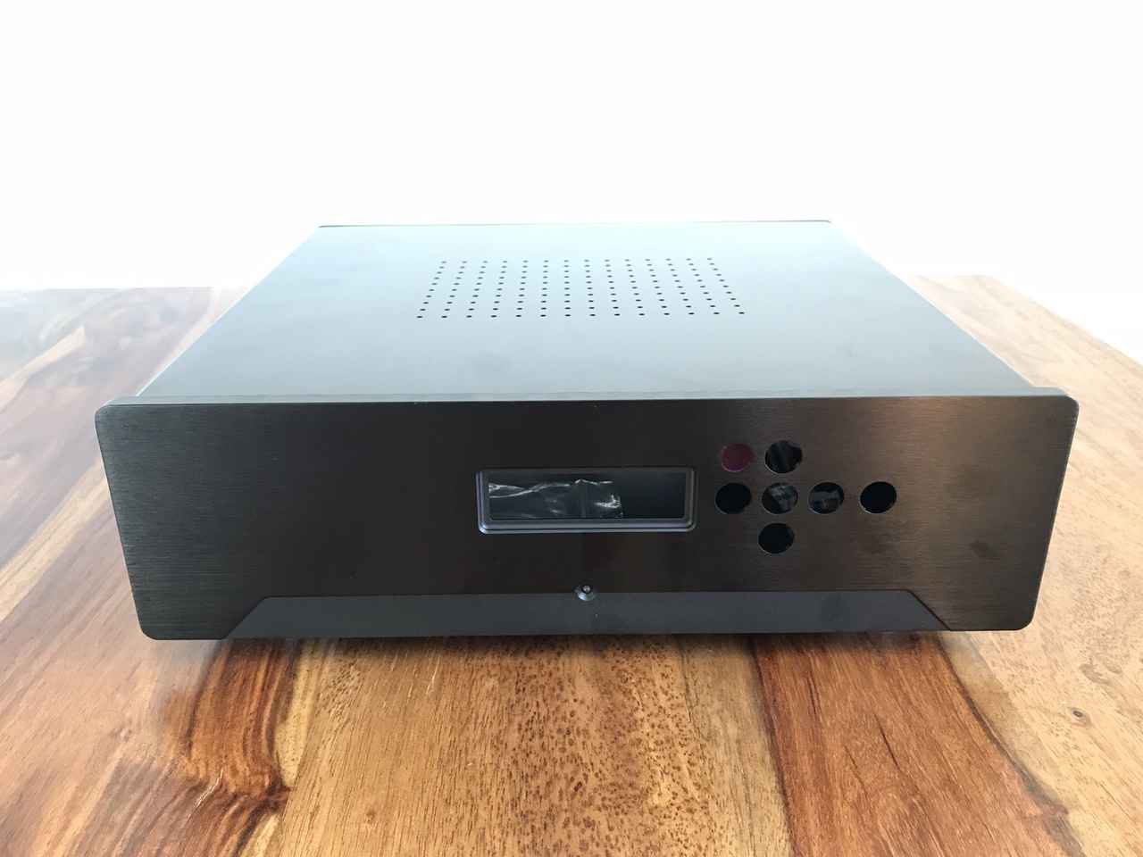
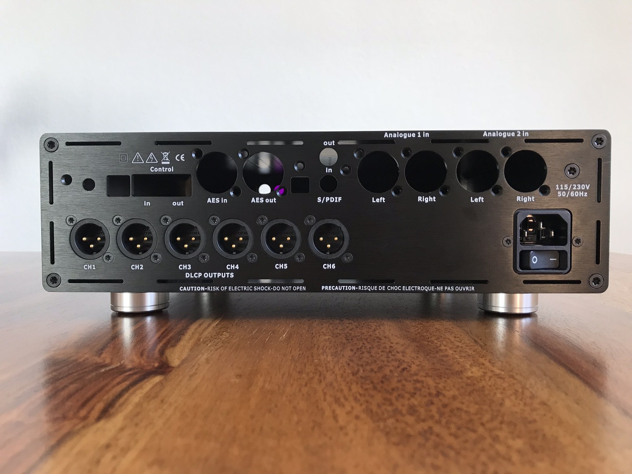
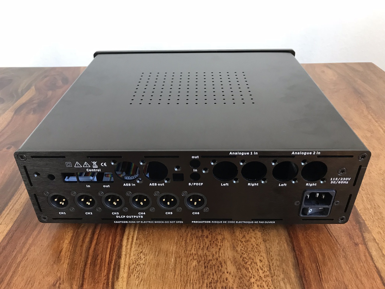
I am considering a 2U case which has DLCP as a pre-amp. Its back panel would naturally have the Hypex Input board (with 4 xlr pair Inputs) and a set of 6 XLR male sockets.
Does any one have such a drawing available, which I could use for CNC? If yes, would be great to get a copy.
Similarly, I am considering a 2U case for Hypex Amps, which uses XLR female sockets for Signal In (6 or 8). I am planning to have 4 Speak-On connectors as Speaker out. Would be great if I could get a copy of this drawing as well, if available.
Thanks in advance.
Hello,
I am considering a 2U case which has DLCP as a pre-amp. Its back panel would naturally have the Hypex Input board (with 4 xlr pair Inputs) and a set of 6 XLR male sockets.
Does any one have such a drawing available, which I could use for CNC? If yes, would be great to get a copy.
Similarly, I am considering a 2U case for Hypex Amps, which uses XLR female sockets for Signal In (6 or 8). I am planning to have 4 Speak-On connectors as Speaker out. Would be great if I could get a copy of this drawing as well, if available.
Thanks in advance.
Last edited:
@ ds23man
Yes, such misleading 'info' ought to have been corrected, especially after Hypex started their diyclassD site and became a lot more "diy friendlier"! Hypex documents harbour many such traps (like vague conventions in naming pins, not clarifying the options available, lack of clear recommendations, to name a few) for the unwary builder.
I believe the DLCP utilises a set of buck/boost kind of converters to take care of the need for various voltages. In such cases theoretically you don't need much except the requisite average voltage and current. However, the question, as always with hobbyists, is exploring the last/least variations in search of improved sound. The dramatic improvement in sound quality as a result of using a good linear PSU for the DLCP was made by someody whom I respect as a 'responsible' DIYer, not given to the usual kneejerk reactions of many. That was the reason I proposed a detailed look into that. (And the last System option I thought of suggesting use linear PSUs.)
At the risk of being pulled up by the Moderators for "soapbox orataory" and philosophising, permit me to touch on a basic aspect:
Virtually all threads in this forum are oriented towards gleaning improved sound, whatever the means adopted. Theoretical requirements are one thing, but none of us has forgotten the many 'mods' that have contributed to an actual measurable and clearly audible improvement in quite a few situations. I am long enough in the tooth to have been familiar with 'big bottles' to the miniscule SMDs. How many triodes sound alike, bias them as you might to the most linear regions? Why this continuing pro/con battles regarding say, Lateral MOSFETs v. VMOSFETs...ordinary transistors v. ring emitter devices...multi-strand wire v. solid core...one sort of caps v. another sort?? The list --and the possibilities-- are seemingly endless. What about that simple line mostly drawn at the bottom of every schematic -- the 'ground' line. Is it as simple as the theoretical need makes it appear to be? Every hobbyist knows the "art and craft" that brings out real performance hiding behind that simple line.
I am not talking about the "High End" (which more often happens to be the "Hype End" these days!) peccadilloes here, but about the genuine advancement in the state of the art that have been brought about by the innate curiosity, talent and 'perspiration' of the many true hobbyists. It is in that spirit that I advocate further experimentation in areas about which most of us believe we know all that is to be known! Let us keep an open mind about reasonable discoveries, and not condemn them without a fair examination by many.
It is often from the 'many little truths' that a fuller picture of the Truth emerges!
My apologies for occupying so much of the thread space.
Warm regards to all.
--UKP
Last edited:
I am not talking about the "High End" (which more often happens to be the "Hype End" these days!) peccadilloes here, but about the genuine advancement in the state of the art that have been brought about by the innate curiosity, talent and 'perspiration' of the many true hobbyists. It is in that spirit that I advocate further experimentation in areas about which most of us believe we know all that is to be known! Let us keep an open mind about reasonable discoveries, and not condemn them without a fair examination by many.
Absolutely - but that is exactly why I am so perplexed by the seeming reluctance of those hobbyists to make even the most elementary measurements and perform objective tests to verify the possible improvements.

Hi there!
Did you complete your project in 2016?
In 2017 I build the LX521.4 and used 2 DLCPs for the filters.
I did not find any ready made filters, so I used the specification of the miniDSP filter design instead to create my own. I would be interested in comparing filter results.
Cheers,
Ronald
Best regards,
Ronald
Ahum,
I intended to send a PM, but made a mistake and posted the question instead. That must be confusing. That said: If there are any LX521.4 owners out there that build filters with DCLP, please send me a PM.
To reflect on some of the recent posts I can share the following from my build with 2 DCLPs in a 10 channel hypex amp.
I use a seperate DCLP SMPS for each DCLP.
Measure voltages for DCLP1 (+15,67 and -16,00) and for DCLP2 (-15,95 and +15,64) Volt.
The DCLP + input board + control board need at maximum a current of 490mA.
Without the boards, you need max 390mA.
The SMPS1200A400 can provide a maximum current of 500mA. However, each amp connected to the SMPS1200A400 also needs current, 40 mA per amp in case of NC400.
I have connected the second DCLP on J2B/J3B in the same case.
You can set switches s3, s5 and s7 to reflect that configuration.
The analog signal is available on J2B.
I'm currently doing listening tests to compare the sound of tos, s/pdif, analogue, usb and AES inputs. Tos support is limited to 96Khz, USB to 48Khz. So for some test cases I will not have results. I use the test samples from 2L High Resolution Music .:. free TEST BENCH and
Test sessions are delayed, as for some reason the DCLP connected to J2B/J3B has trouble with TOS 88/96Khz and S/PDIF 176/192Khz 24bit content. When i swap the DCLPs, the problem stays with the DCLP connected to J2B/J3B. I've not been able to pinpoint a root cause for this.
Currently, I’m running a MiniDSP OpenDRC DA8 for experiments. However, the DA8 is a bit noisy, and as I’ve just ordered a pair of 100dB senitive tweeters, I’m thinking of getting a DLCP.
I’m using an amp based on a pair of UCD180 modules and two UCD32MP for a total of six channels.
The Fusion amps are a temptatin, but I’m wondering if the DLCP can be used as a full function digital preamp for the Fusion amps.
A fully decked DLCP with the addon input board will have 4 analog inputs, 4 digital inputs and two digital outputs.
In the manual, it is stated that
If one of analog inputs is selected, will this be converted and sent to the digital output? And will the volume setting be applied to the ditital output, or does it get the signal at full volume?
I can live with having filters only in the fusion amps, but if the dlcp doesn’t set the volume on the digital outs and doesn’t send on the analog signals, I cannot use it as a preamp for the fusion amps. Then I might as well make it as an integrated, 6ch amp to cover my existing beeds, and tackle the fusion amp setting later.
Johan-Kr
I’m using an amp based on a pair of UCD180 modules and two UCD32MP for a total of six channels.
The Fusion amps are a temptatin, but I’m wondering if the DLCP can be used as a full function digital preamp for the Fusion amps.
A fully decked DLCP with the addon input board will have 4 analog inputs, 4 digital inputs and two digital outputs.
In the manual, it is stated that
.the selected digital input is directly sent to both digital outputs (no filtering).
If one of analog inputs is selected, will this be converted and sent to the digital output? And will the volume setting be applied to the ditital output, or does it get the signal at full volume?
I can live with having filters only in the fusion amps, but if the dlcp doesn’t set the volume on the digital outs and doesn’t send on the analog signals, I cannot use it as a preamp for the fusion amps. Then I might as well make it as an integrated, 6ch amp to cover my existing beeds, and tackle the fusion amp setting later.
Johan-Kr
")
The input module has coax spidf and AES-EBU outputs. They are present on the J2 header. If you look at the system schematic on page 6 of the users manual you can see that the analog inputs go through the ADC and then directly into the DSP, bypassing the digital input portion of the DLCP. So the digital outputs will be full range raw digital signals.
So what you call "digital outputs" does not carry anything that has passed trough a DSP - right?
I have at times wanted to use my own DACs but still the signal processing in the DLCP - that is not possible.
There is digital in for sure - both USB and s/pdif.
Just wanted to avoid confusion of what the DLCP can do - your use of words could maybe be interpreted as if it was possible to connect a DLCP and a plate-amp via a digital interface and still use the DSP processing.
So I suppose the answer to Fenalaar is that - no, the volume will not work lite that as the control board communicates with the DLCP to manipulate the volume - if you want that it must go analogue to the plate amps.
//
Last edited:
There are digital inputs and outputs present on the J2 header on the DLCP itself as well. To me, it looks like the input board is merely switching and routing the inputs to the DLCP. The io board doesn’t have any ADs or other processing, so the limitation is in the DLCP.
Johan-Kr
Johan-Kr
Last edited:
- Home
- Source & Line
- Digital Line Level
- Hypex DSP module(s)