There are DIL header available - basically a chip sized and shaped with solder pins on top. The big suppliers in the UK will have them. Try RS or Farnell.Hi,
Does anyone know of a connector that will plug into the existing socket for the IDC connector that will work with hookup wire (and component leads) instead of ribbon cable?
I'd like my mods to be reversible in case I screw it up!
Thanks.
Hi Jan,
You are correct, I have no input board. It would go straight to the ribbon connector on the main board.
andy
OK, well yes then you need to add the 2.5V common mode voltage.
But remember that the input to the ADC on the DSP board is very low impedance, like 400 ohms IIRC and the level is attenuated by 2/3rds, so you really should add a balanced buffer with some gain that can also generate the CM voltage. Do you need a suitable circuit?
jd
This looks like a contenter
Digi-Key - 609-3003-ND (Manufacturer - 71991-313LF)
There are DIL header available - basically a chip sized and shaped with solder pins on top. The big suppliers in the UK will have them. Try RS or Farnell.
Digi-Key - 609-3003-ND (Manufacturer - 71991-313LF)
I know that several use just a transformer though. Is there something they are skipping?
Don't know, you would have to ask them
")
jd
Last edited:
Hi,
Does anyone know of a connector that will plug into the existing socket for the IDC connector that will work with hookup wire (and component leads) instead of ribbon cable?
I'd like my mods to be reversible in case I screw it up!
Thanks.
What about something like this?
2x13 0.1" Header (26 position IDC ribbon connector) Breakout Board with Screw Terminals - Winford Engineering
Guys,
I have been receiving several emails regarding the transformer outputs that I have implemented in my DCX. I am now in the middle of manufacturing the output board with six balanced channels, using Lundahl transformers and jFet buffers. I have it right now as test board and it works great. Here is the schematic for anyone interested. If you would need PC board let me know, before I place the order.
I have been receiving several emails regarding the transformer outputs that I have implemented in my DCX. I am now in the middle of manufacturing the output board with six balanced channels, using Lundahl transformers and jFet buffers. I have it right now as test board and it works great. Here is the schematic for anyone interested. If you would need PC board let me know, before I place the order.
Attachments
Panomaniac
If you are looking for cheaper alternatives to both Oettle and the Selectronic digital input stage for your DCX2496, I do have PCB to Freeraiders alternative.
Freeraider claim that his stage are very simular to the Selectronic stage.
I am sellingg this boards for $ 5 + shipping. I still have 15 boards, and everyone interested are welcome.
Improved digital input stage for the Behringer DCX2496
Eivind Stillingen, Norway
Guys, I'm going to make this "freerider" alternative stage, and just to be sure I understand the concept, a question: the local oscillator at the PCB should be TCXO with frequency anything above 28M, for instance 33.8688 which is widely available, and the local DSP oscillator 24.576 should be still run as it is or upgraded to better clock - another 24.576 TCXO with it's own PSU. Right?
Here we go:Andy I have the PCB now, but not the bill of materials.
Let's keep each other updated on the project.
Stückliste
----------
* R1 3K SMD
* R2 47K SMD
* R3 47K SMD
* R4 47K SMD
* R5 47K SMD
* R6 47K SMD
* R7 47K SMD
* R8 47K SMD
* R9 47K SMD
R10 330 Ohm
R11 510 Ohm
* R12 3k SMD
* L1 68uH
* C1 1000p SMD
* C2 0.022u SMD
* C3 1000p SMD
* C4 0.1u SMD
C5 22u 6.3V Back Gate
C6 22u 6.3V Back Gate
C7 22u 6.3V Back Gate
* C8 0.1u SMD
* C9 0.1u SMD
* C10 0.1u SMD
* C11 0.1u SMD
* C12 0.1u SMD
* C13 0.1u SMD
* C14 0.1u SMD
* C15 0.1u SMD
* C16 0.1u SMD
C17 22u 6.3V Back Gate
C18 22u 6.3V Back Gate
* IC1 CS8416 Cyrrus Logic
IC2 AD1896 Analog Devices
* IC3 LM2936-Z3.3
* IC4 LM2936-Z3.3
* OSC1 Quarz-Oszillator 28MHz
Guys, I'm going to make this "freerider" alternative stage, and just to be sure I understand the concept, a question: the local oscillator at the PCB should be TCXO with frequency anything above 28M, for instance 33.8688 which is widely available, and the local DSP oscillator 24.576 should be still run as it is or upgraded to better clock - another 24.576 TCXO with it's own PSU. Right?
I'm not sure how much you can save but you get only have of the story (best case (jitter)). You could save much more if you leave it as it is. So you have to make a decision if you want to improve it or if you want to save money. But the way is the goal and I started with the freerider solution too. So keep on going. You will always win experience.
I'm not sure how much you can save but you get only have of the story (best case (jitter)). You could save much more if you leave it as it is. So you have to make a decision if you want to improve it or if you want to save money. But the way is the goal and I started with the freerider solution too. So keep on going. You will always win experience.
Sorry, don't get the point. Could you pls elaborate what you mean?
Sorry, don't get the point. Could you pls elaborate what you mean?
Please read this link: SRC/Clock
You miss the following features:
* Ultra low jitter synchronous master clock (2.6 p Sec. @ 10Hz-20MHz).
* 100% synchronous operation of PLL, SRC, DSP and DACs .
* Sample rates up to 178 kHz
* Two on-board ultra high PSRR (110 dB @10Hz-20kHz) and very low noise (18µV) voltage supplies (improves SRC operation)
* Also SRC design, layout, cable and mounting are improved.
So I would say you'll get less than half of the story with the freerider (and also the Selectronic) solution and even if it's a little bit cheaper you'll decrease your price/performance ratio. Please see also Ergo's measurements.
I do not have any commercial interests. I'm even sending Ward the PCBs for free. But there is donation to Gumyoko montessori school in Ghana. So this might be the reason why my design is a little bit more expensive (if at all?).
My first post - general information on DEQ2496, DCX2496 power supplies. I picked up a unit with a bad power supply (as described) on ebay. The problem was D3 an ultra fast recovery diode rated at 200v. The part number was obsolete. I replaced it with a 400v part with better specs, UF5404 from digikey ($0.75). Problem solved. I am replacing all of my power supplies (8) with an external supply and point of load low noise regulators in the units. My apoligy if i am violating protocol.
Sorry if those are complete noob questions but I'm also about to receive two freerider pcbs and I'm not sure I understand either what brgds tries to do and Oetlle's reply.
When Oettle says "half of the story": what does the freerider board lack? If it's reclocking, I get it yet, the selectronic kit includes that option (that's why I'm confused)
Aren't the freerider board and Pilgham audio's essentially the same design?
Are there any more "surgical" connections needed than those on the pins of the previous src chip? (apart from derived 5v and the replacement of TR1 with a 75Ohm transformer to match spdif specs...this last point being taken care of by the selectronic kit)
Has anybody got a picture of an installed freerider pcb that is clearer than those on the webpage (on which I can't see the power supply to the board)
Thanks!
analog input tweaks
Hy!
Sorry, but my english is very poor.
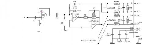
I bought a dcx last week, and I want to do some tweaks. I would like to use the analog inputs, but not in a professional balanced mode, just at home, unbalanced. In the analog input stage a don't like the 47uF trash capacitors, and I want to try remove some opamps.
My question is: What is the most simplier analog input stage in the dcx?
I think the last stage before the A/D converter is needed, bedause the A/D input is balanced...
This is my first plan:
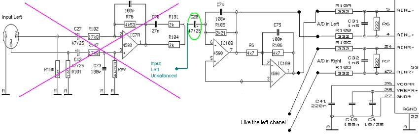
In the green circle I removed the elko, and I replaced an MKT or MKP foil cap.
But it hasn't correct impedances.
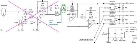
And the second plan:

Or do you have a better idea?
Please help me!
Thank you!
Hy!
Sorry, but my english is very poor.
I bought a dcx last week, and I want to do some tweaks. I would like to use the analog inputs, but not in a professional balanced mode, just at home, unbalanced. In the analog input stage a don't like the 47uF trash capacitors, and I want to try remove some opamps.
My question is: What is the most simplier analog input stage in the dcx?
I think the last stage before the A/D converter is needed, bedause the A/D input is balanced...
This is my first plan:
In the green circle I removed the elko, and I replaced an MKT or MKP foil cap.
But it hasn't correct impedances.
And the second plan:
Or do you have a better idea?
Please help me!
Thank you!
Attachments
- Home
- Source & Line
- Digital Line Level
- Behringer DCX2496 digital X-over