What about this approach? A Constant Current Draw Amplifier with positive feedback instead of the usual cathode decouple cap to raise the amplification.

It seems nearly everyone is using Mr. Fikus Lampizator circuit, which again is an old circuit that I think Mr. Torsten Loesch was one of the first to use for a TDA1541 DAC.
The SRPP circuit. The one I here present has higher amplification and lower output impedance with same use of tube flavour.
Last year I started a thread with some vague ideés and I think SY was closest to the circuit I for the moment are testing at my testbench. common-grid I to V converter
Actually, this could be the first amplifier part in a good phonostage, which uses passive RIAA EQ in between. Again, John Broskie at Tubecad has inspired me")
It seems nearly everyone is using Mr. Fikus Lampizator circuit, which again is an old circuit that I think Mr. Torsten Loesch was one of the first to use for a TDA1541 DAC.
The SRPP circuit. The one I here present has higher amplification and lower output impedance with same use of tube flavour.
Last year I started a thread with some vague ideés and I think SY was closest to the circuit I for the moment are testing at my testbench. common-grid I to V converter
Actually, this could be the first amplifier part in a good phonostage, which uses passive RIAA EQ in between. Again, John Broskie at Tubecad has inspired me
Work in progress
I have corrected some errors on the schematic above. Please update your browsers.
Now there is also the component values I use ftm. (exept I use ECC803S ftm) Gridstoppers could be what you have and you can also lower the output cap to 1uF which then gives -3dB at 15 Hz. Output impedans is 580 ohm teorethical. Anyway it should be low enough for a normal amp after.
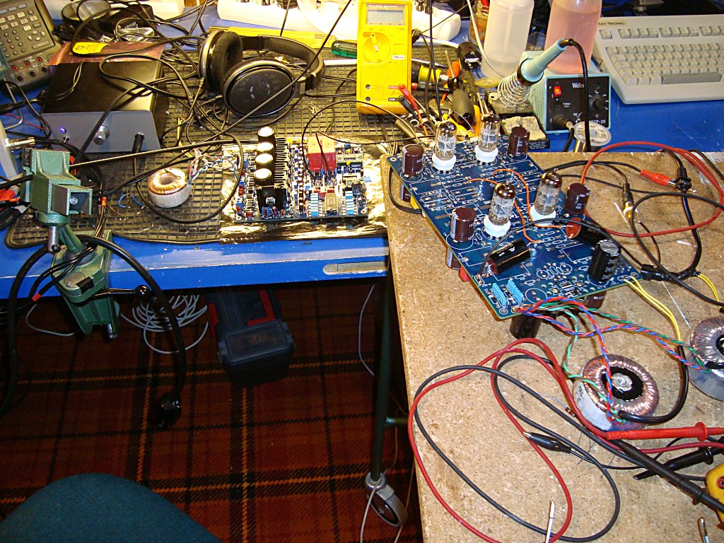
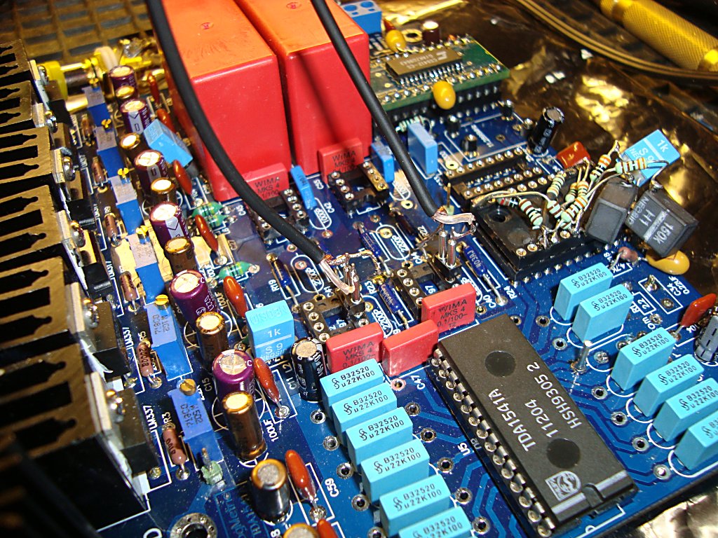
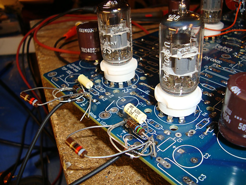
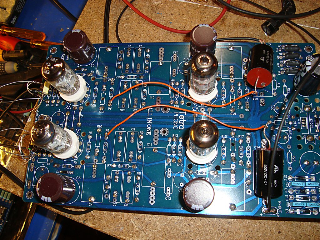
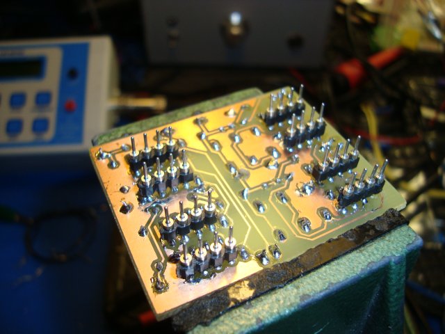
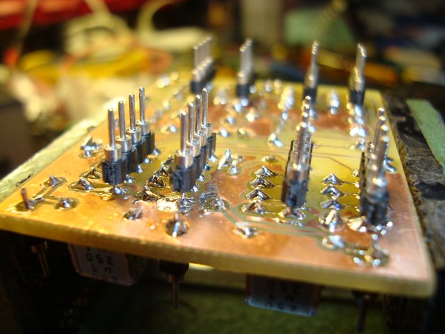
Pictures below reveals my hacking of a beatiful phono kit from John Broskie and Tubecad when testing my idée above. I have longed to get time to do such a phonostage and when John presented this kit this autumn, I bought a PCB and saved some time.
Now it seems I have to do a dedicated PCB for my DAC
How does it sound?
Well, after my last bragging with the sucess of the old Jocko I/V converter I maybe should be more careful with my judgements (it worked really well though)
But this time, believe me, I am over the top.
 This is the biggest leap forward of them all on this DAC. I hear the music in a totally new way. I listen to all my old CD's I know really well, most of them from the -80's and -90's, and sometimes it now reveals character and motion to the music I never thought was on the CD.
When it comes to measuring my laptoop is broken so I have to use my M-Audio external card on some other computer in the house and try to set up a descent test rig. But so far I use my ears and the scope to listen and look at -60dB 1khz (testfile fromPedja Rogic's site) The distorsion is low and the hiss ... isn't much of. I never thought that it could be that silent with tubes but I had my thoughts because this concept for the phono amp was also very silent when it should.
What next?
There is -66mV over the paralelled Allen Bradley resistors. I maybe will test with something there but I really don't think it's necessary.
Test rig and some FFT first of all.
Please feel free to ask or comment. I can take it
I have corrected some errors on the schematic above. Please update your browsers.
Now there is also the component values I use ftm. (exept I use ECC803S ftm) Gridstoppers could be what you have and you can also lower the output cap to 1uF which then gives -3dB at 15 Hz. Output impedans is 580 ohm teorethical. Anyway it should be low enough for a normal amp after.
Pictures below reveals my hacking of a beatiful phono kit from John Broskie and Tubecad when testing my idée above. I have longed to get time to do such a phonostage and when John presented this kit this autumn, I bought a PCB and saved some time.
Now it seems I have to do a dedicated PCB for my DAC
How does it sound?
Well, after my last bragging with the sucess of the old Jocko I/V converter I maybe should be more careful with my judgements
(it worked really well though)But this time, believe me, I am over the top.
This is the biggest leap forward of them all on this DAC. I hear the music in a totally new way. I listen to all my old CD's I know really well, most of them from the -80's and -90's, and sometimes it now reveals character and motion to the music I never thought was on the CD.When it comes to measuring my laptoop is broken so I have to use my M-Audio external card on some other computer in the house and try to set up a descent test rig. But so far I use my ears and the scope to listen and look at -60dB 1khz (testfile fromPedja Rogic's site) The distorsion is low and the hiss ... isn't much of. I never thought that it could be that silent with tubes but I had my thoughts because this concept for the phono amp was also very silent when it should.
What next?
There is -66mV over the paralelled Allen Bradley resistors. I maybe will test with something there but I really don't think it's necessary.
Test rig and some FFT first of all.
Please feel free to ask or comment. I can take it
Monologue continues
Hi all
Didn't get much sleep this night. After some late breakfast and a lot of Coffé I'm back in business again.
So, I was awake this night fiddling with FFT tests and even though the sound was superb there is more distortion with the tubes and probably because of the -66mV at the TDA's output then with OP's and zero volts.
K2 is:
-60dB at 0dB 1khz sample from CD (Pedja Rogic) vs.
-84dB with OP's. Different OP's showed no or little difference.
-66dB i got with Jocko's simple I/V converter. I just have to test that one. In the simple form it's very sensitive to adjust and I'm not into having the time and eager to further develop that circuit, now that I have found that my tubecircuit really get me near what I'm after.
Distortion with -60dB 1khz sample was more then 40dB below for all upper multiples on all measurings. I thought it was wit the -60 dB i should see the most differences because of the small voltage on the I/V resistor. Maybe someone can explain? In the meantime ... more empirical work has to be done.
I'm starting to document all this on my homepage if someone in the future want's a more relaxed reading then the brainstorming such thread as this is
Brainstorming use to have a group of several people throwing idées?
O Brothers where are thou?
New CCD injecting
Going further with this one.
A JFET CCS a'la Pedja solved the -66mV issue and got all available bits on the track.
I have today worked with a homepage for this project. Among other stuff there is FFT graphs of this circuit with and without the CCS injector.
Be my guest.
Going further with this one.
A JFET CCS a'la Pedja solved the -66mV issue and got all available bits on the track.
I have today worked with a homepage for this project. Among other stuff there is FFT graphs of this circuit with and without the CCS injector.
Be my guest.
Studying
Hello samoloko
I have studied Pedjas work a bit and I like his attitude and work. The other ones I have to update myself on. It's the right time know when I'm into it. I think Pedja's approach is hard to beat (as he actually says ). I like it.
The thing is I have allways liked to build something with tubes, because I can. But I'm no freak who is afraid of SS. To combine these things ... me like. It took me 30 years of "thinking" and a lot of "armchair building" before I decided to actually try to build something at all (more then my first guitarr amp) and for a moment disregard all simulations on the PC and also don't listen to all "opinions" on the net for a while.
From that day it started to happend things. At last I now have "my own" tube design for a OTL headphone amplifier I'm very proud of.
The next larger project is this one. I once read a story on Internet of building a DAC with tubed output and was jealous on the guy which had that skill. This was at least 10 or 12 years ago. I can't recall but maybe it was this forums Torsten Loesch? (I can't recall his alias here)
Anyway I think that the SRPP circuit with 100 ohm I/V resistor that nearly everyone use (without compensate the offset over the resistor, so you miss the last bits at low levels) is the best sollution at all.
I really like my circuit because it's a better compromise (maybe subjective... OK). You need a good PSU though because the PSRR isn't the best but on the other hand this circuit is easy with the PSU because it draw a constant current and is not thugging or pushing at the Power supply feeding.
I also have a super reg shunted psu I will use in my final build. It's a DIY group buy that now will come to use. That one has to be tested and verified first though
Anyway, I'm having fun right now and thats the best part.
Hello samoloko
I have studied Pedjas work a bit and I like his attitude and work. The other ones I have to update myself on. It's the right time know when I'm into it. I think Pedja's approach is hard to beat (as he actually says
). I like it.The thing is I have allways liked to build something with tubes, because I can. But I'm no freak who is afraid of SS. To combine these things ... me like
. It took me 30 years of "thinking" and a lot of "armchair building" before I decided to actually try to build something at all (more then my first guitarr amp) and for a moment disregard all simulations on the PC and also don't listen to all "opinions" on the net for a while.From that day it started to happend things. At last I now have "my own" tube design for a OTL headphone amplifier I'm very proud of.
The next larger project is this one. I once read a story on Internet of building a DAC with tubed output and was jealous on the guy which had that skill. This was at least 10 or 12 years ago. I can't recall but maybe it was this forums Torsten Loesch? (I can't recall his alias here)
Anyway I think that the SRPP circuit with 100 ohm I/V resistor that nearly everyone use (without compensate the offset over the resistor, so you miss the last bits at low levels) is the best sollution at all.
I really like my circuit because it's a better compromise (maybe subjective... OK). You need a good PSU though because the PSRR isn't the best but on the other hand this circuit is easy with the PSU because it draw a constant current and is not thugging or pushing at the Power supply feeding.
I also have a super reg shunted psu I will use in my final build. It's a DIY group buy that now will come to use. That one has to be tested and verified first though
Anyway, I'm having fun right now and thats the best part.
Last edited:
would you tell what dac you are using
TDA1541A ?
till now I have tried DIY SRPP with 100 R I/V with Sheldon Stokes tube DAC (pcm63) and find out that this tube stage Is In no terms Hi FI - It Is slow, no highs, no details, no resolution, too tubed sound, not dynamic
but when I moved to Pass D1 out stage It was great Improvement
I really want to try mu follower out stage which have to be much better than SRPP - the gain of 2 times compared to SRPP can be compensated with lowering I/V value
Last edited:
TDA1541A yes.
SRPP is not suitable as an I/V converter for this kind of DAC IMO.
For some reason it's very common used by the DIY community. Maybe because it works and there isn't much other tube schematics of other sollutions out there.
Most people seems to think it's good but you don't. Maybe you have discovered that the high output impedance from a SRPP is getting you problems with capacitances in the connection cable and maybe also the impedance of the amplifier connected after. Could be something you heard.
My schematic is simple but not to simple. A good working sollution with high amplification, pretty low output impedance, compared to the SRPP stage and also the elegant constant current draw of the circuit. You wont need anything more before your endstage.
You need good power supply though. Anyhow, money is no object in that case, is it. My circuit is just CRCRC filtered for the moment.
The sound is ... that kind of liquid feeling you get when listening to a good vinyl setup. The character of instruments and voices is that good I have to listen to all my old CD records again and find out that even the songs I didn't like that much before is joyfull because it's more life in it and the songs sounds different and allmost new. Tubesound? If you mean round wolly and warm, this is not. There is no color at all I think. There is only music ....
I'm over the top flying right now. But I'm not finished ... Last night I piggybacked another TDA1541A on top of the other, with the DEM clocks not shared but syncronised with a 100pF silver mica between the legs 16.
... Thats another story then this Tubecircuit though.
SRPP is not suitable as an I/V converter for this kind of DAC IMO.
For some reason it's very common used by the DIY community. Maybe because it works and there isn't much other tube schematics of other sollutions out there.
Most people seems to think it's good but you don't. Maybe you have discovered that the high output impedance from a SRPP is getting you problems with capacitances in the connection cable and maybe also the impedance of the amplifier connected after. Could be something you heard.
My schematic is simple but not to simple. A good working sollution with high amplification, pretty low output impedance, compared to the SRPP stage and also the elegant constant current draw of the circuit. You wont need anything more before your endstage.
You need good power supply though. Anyhow, money is no object in that case, is it
. My circuit is just CRCRC filtered for the moment.The sound is ... that kind of liquid feeling you get when listening to a good vinyl setup. The character of instruments and voices is that good I have to listen to all my old CD records again and find out that even the songs I didn't like that much before is joyfull because it's more life in it and the songs sounds different and allmost new. Tubesound? If you mean round wolly and warm, this is not. There is no color at all I think. There is only music ....
I'm over the top flying right now. But I'm not finished ... Last night I piggybacked another TDA1541A on top of the other, with the DEM clocks not shared but syncronised with a 100pF silver mica between the legs 16.
... Thats another story then this Tubecircuit though.
Last edited:
Second approach updated on the schematic above
Hi
I discovered that the "injection" of positive feedback gives a pretty high raise (about 10dB) in k2 harmoic distortion together with the 3dB raise in amplification, which we really don't need.
Second approach gives less distortion and still near 2 volts RMS for the next amplifier, your endstage.
I have some more thoughts and are replying to Mr -ecdesigns- on that passive I/V resistor right here. Post #3076.
First I am so happy to see someone working on a passive I/V +tube DAC without the stupid SRPP which has no place in a DAC for the reasons you mentioned. I still think your goal should be the lowest I/V resistor possible with the highest tube gain that is quiet. I have long been considering a PCM1704 with a 10 ohm I/V and two CDA stages (ala Broskies simple phono stage minus RIAA.)
Kudos for pushing the tube DAC envenlope. So for my best results have been a PCM63K with a 6n6p anode follower CCS loaded (similiar to what tent labs discovered.) It had about -80db 2nd harmonic, but the I/V resistor was 47 ohms which is I think too large.
Kudos for pushing the tube DAC envenlope. So for my best results have been a PCM63K with a 6n6p anode follower CCS loaded (similiar to what tent labs discovered.) It had about -80db 2nd harmonic, but the I/V resistor was 47 ohms which is I think too large.
Amasing findings to get really low THD and only 2nd.
Hi regal
I am glad to see that there is at least some souls out there thinking this is interresting.
You have really good THD figures on your setup. 47 ohm is not to large though, so you can sleep safely . 56 ohm gives about 84mV. TDA1541A puts out around 1.5 -1.6mA. I have done exhaustive tests on this lately and they tells me you are safe with 80mV.
For my piggybacked setup (another TDA1541A on top of the other) I now use 27 ohm and then I have 82 - 84mV -0dB 1kHz. FFT shows around -100dB measured on the resistor. You never get better. The spec says -95dB for one TDA1541A.
That means you only need one CCDA stage.
I have done a few more tests lately. I have som excellent E88CC Siemens SQ tubes I wanted to use. They only produce slightly more then 1Volt RMS -0dB but I think that is enough, at least for me using a 4X control preamp after, where I can choose input sources.
This tube gives a super clean sound. I didn't thought it would be possible to hear difference beween -65dB and -87dB K2 measured at -0dB, but it is.
and my latest tests showed some very interresting things.
I got the hint from my simulator program (Multisim 10) and have now a practical knowledge of the phenomenon.
There is a sweet spot when the two tubes is in current balance. The first tubes cathode resistor (R2 on the schematic first post) should be a potentiometer so that you can adjust it if the tubes are not 100% matched.
There is another sweet spot which was really amasing and quite shocking discovery
  (I did'nt get really frighten though )
The E88CC setup of this CCDA amp really likes to be loaded a bit. My tests showed around 4.1k for the R6 resistor outside the output capacitor. It dropped the THD from around -77dB to -87 dB! And more, no other harmonic then the second order was visible! In my case, using a R2R ladder volumepot after which loads the source with 10k I have to choose right resistor there as well or maybe have a pot. I now have THD figures with this tubed I/V CCDA, that runs circles around OP amps. I didn't even in my fantasy expect to get that good measuring figures out of such a simple circuit, not even using global feedback.
The sound is also fantastic. If you have good CD recordings it is very clean. It's also easier to find which recordings are not that good.
I have to go back to the bench again. Documentation on this last findings will be updated later on on my homepage.
Hi regal
I am glad to see that there is at least some souls out there thinking this is interresting.
You have really good THD figures on your setup. 47 ohm is not to large though, so you can sleep safely
. 56 ohm gives about 84mV. TDA1541A puts out around 1.5 -1.6mA. I have done exhaustive tests on this lately and they tells me you are safe with 80mV.For my piggybacked setup (another TDA1541A on top of the other) I now use 27 ohm and then I have 82 - 84mV -0dB 1kHz. FFT shows around -100dB measured on the resistor. You never get better. The spec says -95dB for one TDA1541A.
That means you only need one CCDA stage.
I have done a few more tests lately. I have som excellent E88CC Siemens SQ tubes I wanted to use. They only produce slightly more then 1Volt RMS -0dB but I think that is enough, at least for me using a 4X control preamp after, where I can choose input sources.
This tube gives a super clean sound. I didn't thought it would be possible to hear difference beween -65dB and -87dB K2 measured at -0dB, but it is.
and my latest tests showed some very interresting things.
I got the hint from my simulator program (Multisim 10) and have now a practical knowledge of the phenomenon.
There is a sweet spot when the two tubes is in current balance. The first tubes cathode resistor (R2 on the schematic first post) should be a potentiometer so that you can adjust it if the tubes are not 100% matched.
There is another sweet spot which was really amasing
and quite shocking discovery (I did'nt get really frighten though )The E88CC setup of this CCDA amp really likes to be loaded a bit. My tests showed around 4.1k for the R6 resistor outside the output capacitor. It dropped the THD from around -77dB to -87 dB! And more, no other harmonic then the second order was visible! In my case, using a R2R ladder volumepot after which loads the source with 10k I have to choose right resistor there as well or maybe have a pot. I now have THD figures with this tubed I/V CCDA, that runs circles around OP amps. I didn't even in my fantasy expect to get that good measuring figures out of such a simple circuit, not even using global feedback.
The sound is also fantastic. If you have good CD recordings it is very clean. It's also easier to find which recordings are not that good.
I have to go back to the bench again. Documentation on this last findings will be updated later on on my homepage.
Last edited:
FFT on calibrated E88CC CCDA circuit
This is a FFT from last night findings, described in the post above.
bmp.jpg)
Today I also did both channels calibrated with those E88CC tubes (6DJ8, 6922, or ECC88 is equivalents) and is right now listening at it.
And because it's saturday I also have a few beer as companion to the music. It sounds even better then (subjective I know )

Couldn't get quite that low third order THD today though.
On the other hand I don't have any LP filter at all, running NOS. I'm intending some -12dB at 44.1kHZ with the finished project.
I also don't have any main AC filtering at all on any of the tests done so far.
Maybe a 220V AC cleanup could bring a few dB, I don't know.
Have a nice weekend and please, go get it for yourself with the solder iron! I mean the Nirvana of satisfaction when you built something of your own that whips out most of the competitors 
Over and out for some time.
This is a FFT from last night findings, described in the post above.
Today I also did both channels calibrated with those E88CC tubes (6DJ8, 6922, or ECC88 is equivalents) and is right now listening at it
.And because it's saturday I also have a few beer as companion to the music. It sounds even better then (subjective I know
)Couldn't get quite that low third order THD today though.
On the other hand I don't have any LP filter at all, running NOS. I'm intending some -12dB at 44.1kHZ with the finished project.
I also don't have any main AC filtering at all on any of the tests done so far.
Maybe a 220V AC cleanup could bring a few dB, I don't know.
Have a nice weekend and please, go get it for yourself with the solder iron!
I mean the Nirvana of satisfaction when you built something of your own that whips out most of the competitors Over and out for some time.
Last edited:
project is progressing
Hi habsrock93
This DAC is awsome.
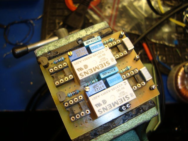
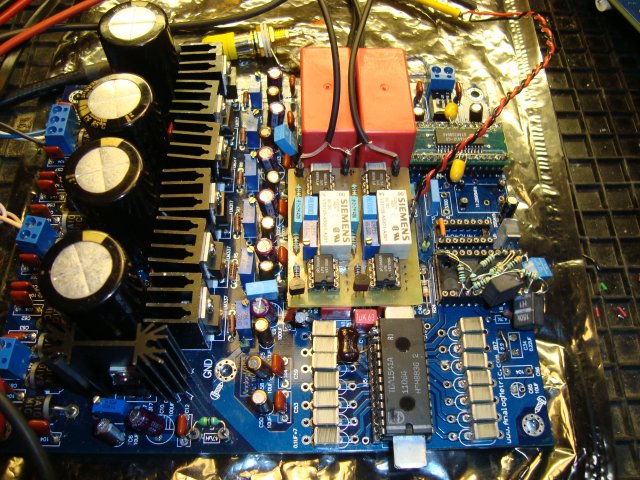
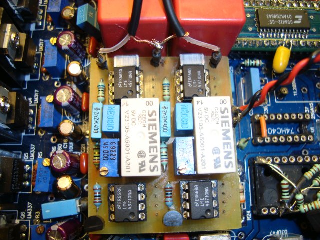
I have since my last post done some Eagle CAD and etched a PCB which I piggybacked on top of the four OP IC-holders. On top of that card I have the I/V resistor and a LP filter for the tubecircuit. There is also two High quality relays so that I can switch between tubed output or SS with the OP's.
I have settled for the lower amplifying device E88CC. So now my DAC gives 1.1V RMS, both with the LME49710 and the tubes. I have also altered the LPF and feedback on the OP's to match the tube circuit. So when switching there should be very little difference in amplitude or frequencey response. Just comparing other signatures which is hard to measure.
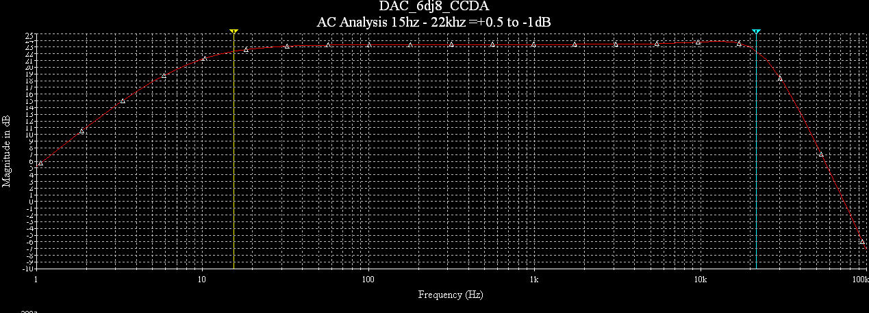
I'm not finished but I have even lower THD figures know, with both the OP's and the tubes. Superclean sound and very high revealing of details. My latest LPF approach which gives -12dB att 44.1Khz, still maintaining -0.5dB at 20Khz did a bit to the upper frequencys for this NOS setup I use. I handpicked and mesured all of those components to get exat the same phase response on both channels.
More info and pictures later on. FTM I'm in the middle of doing a genealogy death register of people that died between 1901 and 1946 in the Parish I live. Talk about different hobbies ...
Hi habsrock93
This DAC is awsome.
I have since my last post done some Eagle CAD and etched a PCB which I piggybacked on top of the four OP IC-holders. On top of that card I have the I/V resistor and a LP filter for the tubecircuit. There is also two High quality relays so that I can switch between tubed output or SS with the OP's.
I have settled for the lower amplifying device E88CC. So now my DAC gives 1.1V RMS, both with the LME49710 and the tubes. I have also altered the LPF and feedback on the OP's to match the tube circuit. So when switching there should be very little difference in amplitude or frequencey response. Just comparing other signatures which is hard to measure.
I'm not finished but I have even lower THD figures know, with both the OP's and the tubes. Superclean sound and very high revealing of details. My latest LPF approach which gives -12dB att 44.1Khz, still maintaining -0.5dB at 20Khz did a bit to the upper frequencys for this NOS setup I use. I handpicked and mesured all of those components to get exat the same phase response on both channels.
More info and pictures later on. FTM I'm in the middle of doing a genealogy death register of people that died between 1901 and 1946 in the Parish I live. Talk about different hobbies ...
Yes it will. I think you will have problems with a to high output impedance. Put a cathode follower after and you end up like me .... with a CCDA amplifier. Nothing to be ashamed ofI had planned on building the output with an anode follower. Could be interesting comparing results!
Back on track again
I'm sorry if I have bothered you with other stuff after my first post in this thread. It's so many things to test before you finalize the project.
So now I'm back on track again.
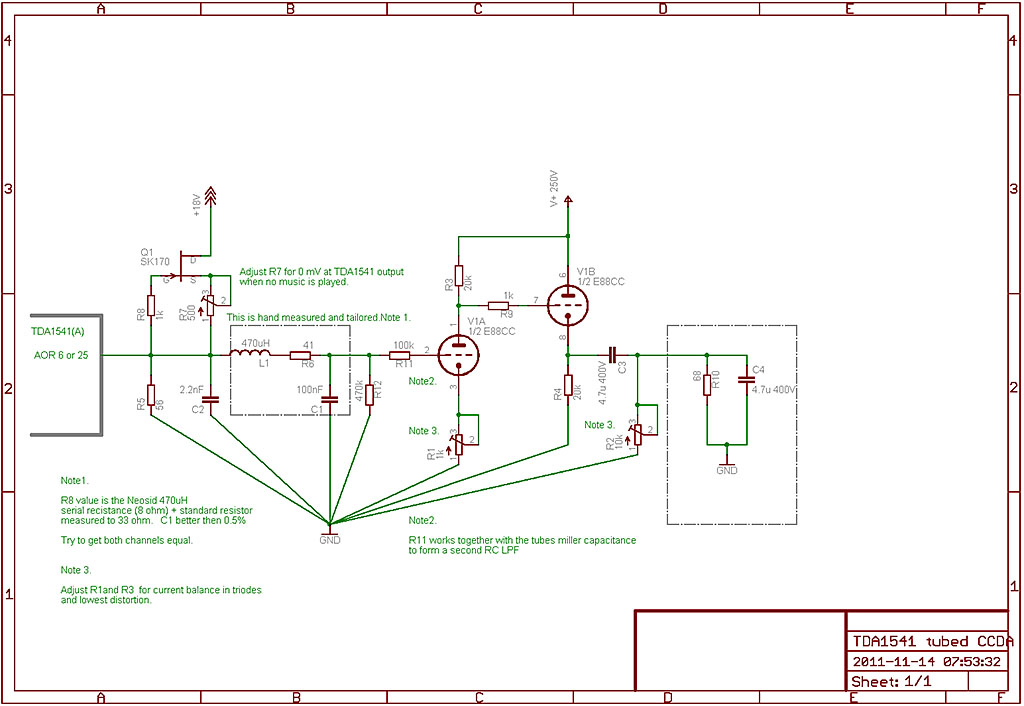
I here present the final (?) schematic on my CCDA tubestage I have done research on lately.
This is the one I'm listening to right now on the testbench.
The schematic is for the output of one TDA1541A. For the moment I use two piggybacked DAC's and therefore have 27 ohm as an I/V resistor.
I have my tubes including the first 470k gridbias resistor and the 100k gridstopper connected trough screened cables to the other parts with the CCS and LPF filter. (Those parts sits on my new, also piggybacked, toggling card. The one I mentioned above where I now can switch between tubes and OP's.)
Schematic is telling the rest. Please feel free to try. You won't be dissapointed.
I'm sorry if I have bothered you with other stuff after my first post in this thread. It's so many things to test before you finalize the project
.So now I'm back on track again.
I here present the final (?) schematic on my CCDA tubestage I have done research on lately.
This is the one I'm listening to right now on the testbench.
The schematic is for the output of one TDA1541A. For the moment I use two piggybacked DAC's and therefore have 27 ohm as an I/V resistor.
I have my tubes including the first 470k gridbias resistor and the 100k gridstopper connected trough screened cables to the other parts with the CCS and LPF filter. (Those parts sits on my new, also piggybacked, toggling card. The one I mentioned above where I now can switch between tubes and OP's.)
Schematic is telling the rest. Please feel free to try. You won't be dissapointed.
- Status
- This old topic is closed. If you want to reopen this topic, contact a moderator using the "Report Post" button.
- Home
- Source & Line
- Digital Line Level
- Tubed CCDA I/V Amp for TDA1541(A)