ESS DAC
Yes, it also appears ahead of time with sampling rates up to 1.5MHz and DSD support! Transports with 768KHz are only just appearing, so quite a lot of catching up to do.
Hi all
Anyway, It sound like ESS is still the best DAC around ...
Yes, it also appears ahead of time with sampling rates up to 1.5MHz and DSD support! Transports with 768KHz are only just appearing, so quite a lot of catching up to do.
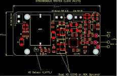
Synchronous Master Clock
Ok, this is not a new concept but a DAC system with its master clock synchronized with the source/transport clock has better jitter performance than one that is independently clocked (async) The Sabre DACs ( with all its jitter reduction technology) also benefit from such arrangement of synchronous clocking. A-B comparison showed improved detailed when synchronously clocked. Others have similarly reported such benefits.
The simplest implementation is to slave the DAC clock from the transport clock (usually 11-24MHz). In this case transport is the Master. Works fine with low sampling rates ( up to 96-176Khz) but the Sabre DACs require higher clock frequency than the transport clock at higher sampling rates for best results (jitter reduction).
For 384KHz or higher sampling rate we are looking at ~100MHz DAC master clock. So use a 98.304MHz for the DAC clock that is an integral multiple of a typical transport clock and then divide this output by 4 to match the 24.576MHz of the transport XO. After this slave the transport with this divided but perfectly edge-synchronized clock. (So DAC clock is Master)
Things can get complicated though with most transports having 2 or even 3 clocks to cover the full range of sampling rates. So the multiple switching needs to be implemented in a design like the AKX Clock module.
Hope this helps.
More updates to come.
Can I get some more informations about Synchronous Master Clock AKX Series? how to switch 44.1k / 48k, buffered or not, etc...
Ok, this is not a new concept but a DAC system with its master clock synchronized with the source/transport clock has better jitter performance than one that is independently clocked (async) The Sabre DACs ( with all its jitter reduction technology) also benefit from such arrangement of synchronous clocking. A-B comparison showed improved detailed when synchronously clocked. Others have similarly reported such benefits.
The simplest implementation is to slave the DAC clock from the transport clock (usually 11-24MHz). In this case transport is the Master. Works fine with low sampling rates ( up to 96-176Khz) but the Sabre DACs require higher clock frequency than the transport clock at higher sampling rates for best results (jitter reduction).
For 384KHz or higher sampling rate we are looking at ~100MHz DAC master clock. So use a 98.304MHz for the DAC clock that is an integral multiple of a typical transport clock and then divide this output by 4 to match the 24.576MHz of the transport XO. After this slave the transport with this divided but perfectly edge-synchronized clock. (So DAC clock is Master)
Things can get complicated though with most transports having 2 or even 3 clocks to cover the full range of sampling rates. So the multiple switching needs to be implemented in a design like the AKX Clock module.
Hope this helps.
More updates to come.
Things can get complicated though with most transports having 2 or even 3 clocks to cover the full range of sampling rates. So the multiple switching needs to be implemented in a design like the AKX Clock module.
Hope this helps.
More updates to come.
several well-known low-phase noise oscillators - such as Crystek CCHD-957 - has a pin for enable/disable function, and several transports/USB DDC uses this
function for switching clocks if they has 2 clocks for 44.1k fs and 48k fs family.
For example, SDtrans384(sd card digital transport) has output pins for
enable/disable signal in order to control switching when using external 22.5792mhz/24.576mhz clocks.
So that I think it might be helpful for switching 2 or more if AKX clock module could accept such E/D signal.
Of course, tapping these enable/disable signal from transports might be not so
easy.
Regards.
Synchronous Master Clock
The AKX has input switching functions that can take signals from transports and select XOs that has enable/disable functions. The CCHD-957 is a good candidate for these functions but has only up to 50MHz types. I would like to cover up to 100MHz with similar super low phase noise specs. NDK's XO is an option but getting sample quantities for DIY folks can be a problem. Looking for 98.304MHz and 90.3168MHz. Anyone can help source samples?") .
.
Also transports without the above outputs can be a problem and may require mods to tap signals from processor chips or even use the DAC controller (like AKC12) to monitor sample rates and switch the AKX
The AKX has input switching functions that can take signals from transports and select XOs that has enable/disable functions. The CCHD-957 is a good candidate for these functions but has only up to 50MHz types. I would like to cover up to 100MHz with similar super low phase noise specs. NDK's XO is an option but getting sample quantities for DIY folks can be a problem. Looking for 98.304MHz and 90.3168MHz. Anyone can help source samples?
. Also transports without the above outputs can be a problem and may require mods to tap signals from processor chips or even use the DAC controller (like AKC12) to monitor sample rates and switch the AKX
can the MCU be used for this function with only a firmware upgrade? would it be able to use its usb connection to sense these changes? titan is able to send these cues
so looks like i'm covered, i can already use titan for master, but clock distribution is causing me some problems
you can get sample quantities of the NDK at ch1pstop.com but they need several weeks to fulfil the order. at least thats how i understand it
• When in slave mode, outside clock generator (or DAC/ADC module) must change the frequency accord- ing to the signal of “CLK_SEL” . CLK_SEL will set LOW when Master clock input needs to be 44.1K* 512 or 44.1K * 1024 Hz. It will set HIGH when Master clock input needs to be 48K* 512 or 48K * 1024 Hz
so looks like i'm covered, i can already use titan for master, but clock distribution is causing me some problems
you can get sample quantities of the NDK at ch1pstop.com but they need several weeks to fulfil the order. at least thats how i understand it
Last edited:
Sync Clock
I have not checked this Lightharmonic Titan module as it appears is not available for DIY use. Will look into it and advise soon.
The following Transports can be supported (mods and required):
1. AKU24 (Hiface)
2. EXA2UI
3. USBPAL
4. SDTrans384
Thanks, will check Ch1pstop for NDK XO samples.
can the MCU be used for this function with only a firmware upgrade? would it be able to use its usb connection to sense these changes? titan is able to send these cues
I have not checked this Lightharmonic Titan module as it appears is not available for DIY use. Will look into it and advise soon.
The following Transports can be supported (mods and required):
1. AKU24 (Hiface)
2. EXA2UI
3. USBPAL
4. SDTrans384
Thanks, will check Ch1pstop for NDK XO samples.
the quote was from the manual, so if a pullup logic low or high can be used to trigger a switch between clocks on the new module it would seem possible to use.
i can test if it works, or perhaps take a peek at the voltages present on the CLK_SEL pin when a change in sample rate is required. i dont see why it wouldnt, one presumes thats why the CLK_SEL pin was put there in the first place
if you are making an order for the NDK units, can you please count me in for a couple? i'll split shipping
Last edited:
The AKX has input switching functions that can take signals from transports and select XOs that has enable/disable functions.
Nice!
That AKX sounds pretty handy!
I had a question about the upcoming AKD16. Is it a similar setup to the AKD18 but without the need for external IV stage? Will it be capable of handling similar multichannel i2s inputs? Is the IV on the pcb or integrated into the ES9016 chip? I'm looking to take i2s signal from a minidsp and trying to keep system complexity down a bit so integrated IV appeals to me. I will need 6ch for a 3way active setup.
I had a question about the upcoming AKD16. Is it a similar setup to the AKD18 but without the need for external IV stage? Will it be capable of handling similar multichannel i2s inputs? Is the IV on the pcb or integrated into the ES9016 chip? I'm looking to take i2s signal from a minidsp and trying to keep system complexity down a bit so integrated IV appeals to me. I will need 6ch for a 3way active setup.
9016 DAC AKD16
The AKD16 series DAC based on 9016 chip will be offered with more integration like IV and controller on-board. (There is no IV on chip). The digital inputs are the same as 9018 DAC. At this stage 2CH is planned but 8CH version can be done if there is sufficient interest.
That AKX sounds pretty handy!
I had a question about the upcoming AKD16. Is it a similar setup to the AKD18 but without the need for external IV stage? Will it be capable of handling similar multichannel i2s inputs? Is the IV on the pcb or integrated into the ES9016 chip? I'm looking to take i2s signal from a minidsp and trying to keep system complexity down a bit so integrated IV appeals to me. I will need 6ch for a 3way active setup.
The AKD16 series DAC based on 9016 chip will be offered with more integration like IV and controller on-board. (There is no IV on chip). The digital inputs are the same as 9018 DAC. At this stage 2CH is planned but 8CH version can be done if there is sufficient interest.
Hi Acko and all,
How would I go about connecting the ackodac in 4 channel quad mode? I have the 8 channel version. I will be connecting it to the exa transport via i2s. Also, as far as register settings, what are the optimal settings for my configuration? I want to run with the ASRC and oversampling on.
thanks,
Will
Crossposting:
I just finished my ackoDAC with tube out:
http://www.diyaudio.com/forums/digital-line-level/196552-buffalo-iii-dac-tube-output-stage-9.html
Bruno
I just finished my ackoDAC with tube out:
http://www.diyaudio.com/forums/digital-line-level/196552-buffalo-iii-dac-tube-output-stage-9.html
Bruno
Crossposting:
I just finished my ackoDAC with tube out:
http://www.diyaudio.com/forums/digital-line-level/196552-buffalo-iii-dac-tube-output-stage-9.html
Bruno
Hi Bruno,
Thanks for sharing. fantastic effort!. If I am not mistaken this DAC board is a special build with a 9018 chip instead with outputs combined in stereo.
Also, looking closely your SDATA from transport goes to only one input of the DAC. The original manual indicated just this but I have since update manual as below:
"Stereo PCM I2S sources have 3 signals, Bit Clock, Word Clock and DATA. The Bit Clock (BCK) goes to 'CK', Word Clock (LRCK) to D1 and DATA to D2, D3, D4, D5 of the Digital Inputs of this DAC module."
So you are loosing dynamic range and output level with only one input connected.
Sorry I did not update you on this but I did post on the above sometime back.
Will send you the updated manual.
Hi Bruno,
...
Also, looking closely your SDATA from transport goes to only one input of the DAC. The original manual indicated just this but I have since update manual as below:
"Stereo PCM I2S sources have 3 signals, Bit Clock, Word Clock and DATA. The Bit Clock (BCK) goes to 'CK', Word Clock (LRCK) to D1 and DATA to D2, D3, D4, D5 of the Digital Inputs of this DAC module."
So you are loosing dynamic range and output level with only one input connected.
...
Or you could try setting the quantizer to 9bit (which also enables internal source sharing)
Or you could try setting the quantizer to 9bit (which also enables internal source sharing)
Of course, yes, the undocumented feature of the 9018/12 Sabre chips. Thanks GLT.
Hi GLT,
How would I set the register for 8bit quatization, as that is the way I would like to implement my quad set up. This sets up register 15, but how does this differ-compare to the reg 14 setting that is documented for ackodac? Do both of these give me the input sharing? Can I use one or the other or both? Does quatization also give me better noise characteristics? I would then combine the outputs 1,3 2,4 5,7 6,8 ?
thanks,
Will
Hi GLT,
How would I set the register for 8bit quatization, as that is the way I would like to implement my quad set up. This sets up register 15, but how does this differ-compare to the reg 14 setting that is documented for ackodac? Do both of these give me the input sharing? Can I use one or the other or both? Does quatization also give me better noise characteristics? I would then combine the outputs 1,3 2,4 5,7 6,8 ?
thanks,
Will
You can find the settings for the quantization here: Sabre32 H i F i D U I N O
Quantizer is reg15
Rerouting is reg14
Both will result in using 1/2 the inputs, but only 8 bit quantizer will turn off 1/2 of the internal digital logic. This "lowers out of band noise".
You can do both with no harm
You can read more here: Sabre32: Effect of Quantizer Setting H i F i D U I N O
PS: I don't claim to know the theory of what is going on internally. Just collecting and passing along what others have said and when I can, I test it too
- Status
- This old topic is closed. If you want to reopen this topic, contact a moderator using the "Report Post" button.
- Home
- Source & Line
- Digital Line Level
- ackoDAC based on ES9018