Nice. Did you find that heatsinks on the regulators were necessary?
Yes for 3.3V Reg and +15V on the PS. The others are not really neccesary.
After listening a time I found out there is a distortion im mid/high. Does anybody has an idea what this could come from ?
I think I need to check with a scope next days..
regards Michael
After listening a time I found out there is a distortion im mid/high. Does anybody has an idea what this could come from ?
I think I need to check with a scope next days..
regards Michael
Do you mean it got worse, which would indicate an electrical problem, or do you think it is intrinsic to the sound? I've never really noticed any particularly harsh characteristics. Maybe my ears are not sensitive enough.
Do you mean it got worse, which would indicate an electrical problem, or do you think it is intrinsic to the sound? I've never really noticed any particularly harsh characteristics. Maybe my ears are not sensitive enough.
Evan you're absolutelty right, its is an electrical prob.
I changed the Preamp and now it's sounding wonderful.
")
Thanks for help. Only wondering why there is a problem with SAC Epsilon.
?? Output / Input Impedance
regards Michael
Evan you're absolutelty right, its is an electrical prob.
I changed the Preamp and now it's sounding wonderful.
Glad to hear it...or maybe you're glad to hear it.
Yes, I think it would be good to use a separate lower voltage transformer for the digital supplies.Yes for 3.3V Reg and +15V on the PS. The others are not really neccesary....
Glad to hear it...or maybe you're glad to hear it.
Today I checked again and found the damned mistake.
The output resistors I put in had 24K9 instead of 24R9, so everything is
clear about that overdriven amp.
Now my ezdac is really working and sounding great !
Evan I hope now you understand my yesterdays post.
regards Michael
Update on progress,
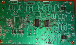
I have installed most of the smd's except for a few around U1 and C15, I'll put them in after U1 is in, I'm waiting on the rest of the parts to arrive. Those tiny caps were a real pita, they were worse than the IC's. I do have a couple of questions.
On the btm right below C20' I'm guessing that is where U6 with the three legs goes, am I correct ?
Has anyone installed another clock for U7 other than the one's in the BOM ? Is there any available that could fit on the board that would make a difference ?
Attachments
You need good magnification, small tweezers, thin solder, and a thin iron to do them. I apply solder onto one pad, then slide in the SMD part from the other side as I'm re-heating the pad. Then solder the other side, and come back to the first side and re-flow, applying more solder if necessary. Sometimes you need to push down gently on the part while re-flowing one side or the other, to make sure the part is flat on the PCB.Those tiny caps were a real pita, they were worse than the IC's.
flux flux and more flux is my secret for SMD, makes it so much easier to get a nice shiny smooth joint. can be a bit of a pain to clean later, but I find it worthwhile as it also means much less time is needed to get solder to flow properly meaning the chips are subjected to less heat. for tiny SMD caps and R's, the price of a high quality pair of tweezers (actually I have both straight and curved type) are worth their weight in gold
Last edited:
On the btm right below C20' I'm guessing that is where U6 with the three legs goes, am I correct ?
Has anyone installed another clock for U7 other than the one's in the BOM ? Is there any available that could fit on the board that would make a difference ?
Yep, that's the place for U6. It's a bit tight, so close to the capacitor.
The v1.5 board can hold a standard half-brick oscillator and an SMD type. For the half-brick, at this frequency the options are limited at most suppliers, if you can get one at all. Your best option here is a Tentlabs XO, that will run on 3.3V as well, and is indeed a low-jitter component.
In SMD, you need a 5x7mm. part. There are a few suppliers that actually specify some form of jitter, so getting the lowest one seems logical. You can leave the ones that don't spec anything here. The frequency stability, mostly indicated in 50, 25 or 10ppm is often promoted as THE MOST important factor, but this is the long-term stabilty and has nothing to do with jitter.
For example: Farnell 1640947 and 1641004 or Digi-Key 631-1120-1-ND, 887-1173-1-ND, CW449CT-ND, CW528CT-ND, 535-10077-1-ND, 631-1186-1-ND and CTX326LVCT-ND.
And then there's the DeLuxe solution: The Flea
Regards,
Ray
Hi Michael,
I can report that the ezDAC benefits from having separate, low-noise power supplies. My first DAC used one simple 9V supply (with 7809) for the 3.3V and 5V sections, and a +/-15V supply to power the analog supplies.
The DAC sounds very good in this configuration, but now I have upgraded it with four Super Teddy Regulators and it has opened-up even more. I removed the on-board LM317/337 regulators. Music sounds more "fluid", with nice open soundstage and very silent background.
Regards,
Ray
Last edited:
Hi Guys,
Are the optional current regulator diodes CRDL and CRDR worthwhile putting into the DAC ? I forgot to order them but will if they are worth it.
Thanks,
PJN
I've never actually used them. I got the idea from Tangentsoft, who suggests it as one way to bias op amps into Class A operation, and thought it would be harmless to put that as an option. If you try it (or anyone else here has tried it), I'd love to hear about it.
USB-SPDIF adapter
Here is the schematic of the USB adapter I'm working on. Its primary purpose is to drive the ezdac, with the option of either USB or S/PDIF inputs (selected by a small relay).
I've also added a direct audio output to make it more versatile. I have 300-ohm headphones, and need a bit of gain to drive them from a DAC, so I've added opamps and a +/- supply.
Comments are welcome. I may start a separate thread for this PCB, not wanting to pollute this one.
Attachments
Comments are welcome. I may start a separate thread for this PCB, not wanting to pollute this one.
Cool. I think you should start a new thread, but only because there is probably a much wider audience that will be interested. I've actually received numerous e-mails in the past of people wanting to know if there's a good USB->SPDIF converter.
Done. Here it is:Cool. I think you should start a new thread, but only because there is probably a much wider audience that will be interested. I've actually received numerous e-mails in the past of people wanting to know if there's a good USB->SPDIF converter.
http://www.diyaudio.com/forums/digital-line-level/161541-usb-s-pdif-converter-dac.html
- Status
- This old topic is closed. If you want to reopen this topic, contact a moderator using the "Report Post" button.
- Home
- Source & Line
- Digital Line Level
- ezDAC v.1.5 Builders Thread