Most CD drives and players with SPDIF out do employ pulse transformers.
The PT is used of two reasons.
First of all it is often used as a step down transformer from the standardised ~3V to ~1V out.
Next it provides insulation and protection.
The downside of using PT´s is mainly hysteresis and thus jitter.
I´ve been trying a few experiments that occasionly might work for some.
I exchanged the PT with a resistor network, actually it is a simple voltage devider. To lower the output voltage 390 Ohm in series with the output is adequate, after that you put 90 Ohms parallel to ground. Thus you have 75 Ohms output impedance and 1V out.
But remember, you now connected your groundplane in your DAC with the groundplane in your source.
Don´t do that with a computer or any other source employing SMPS, it might be fatal to your DAC.
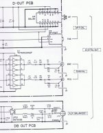
In the supplied scematic of the SPDIF out of a Denon DCD3560, it is obvious that this digital output was not intended for external conversion at all, it was more likely designed for recording use or something like that, as the external DAC was simply not invented at the time this CD player was designed.
But nowadays the design of digital outputs unfortunally is mostly the same.
Some small comapnies tried to make a difference http://www.scientificonversion.com is a company like that.
The CD player has in fact 2 SPDIF outlets, which makes it possible to compare Transformerless output with non transformerless output with ease. I recomend you try this out.
My impression is that a pulsetransformer in the SPDIF simply ads a small amount of bathroom sound to the signal.
I have seen the signals on oscilloscope, and the transformerless signal does not contain any ringing as the transformercoupled does. The difference is visually remarkable.
Would be nice anyone else did experience the same thing
The PT is used of two reasons.
First of all it is often used as a step down transformer from the standardised ~3V to ~1V out.
Next it provides insulation and protection.
The downside of using PT´s is mainly hysteresis and thus jitter.
I´ve been trying a few experiments that occasionly might work for some.
I exchanged the PT with a resistor network, actually it is a simple voltage devider. To lower the output voltage 390 Ohm in series with the output is adequate, after that you put 90 Ohms parallel to ground. Thus you have 75 Ohms output impedance and 1V out.
But remember, you now connected your groundplane in your DAC with the groundplane in your source.
Don´t do that with a computer or any other source employing SMPS, it might be fatal to your DAC.
In the supplied scematic of the SPDIF out of a Denon DCD3560, it is obvious that this digital output was not intended for external conversion at all, it was more likely designed for recording use or something like that, as the external DAC was simply not invented at the time this CD player was designed.
But nowadays the design of digital outputs unfortunally is mostly the same.
Some small comapnies tried to make a difference http://www.scientificonversion.com is a company like that.
The CD player has in fact 2 SPDIF outlets, which makes it possible to compare Transformerless output with non transformerless output with ease. I recomend you try this out.
My impression is that a pulsetransformer in the SPDIF simply ads a small amount of bathroom sound to the signal.
I have seen the signals on oscilloscope, and the transformerless signal does not contain any ringing as the transformercoupled does. The difference is visually remarkable.
Would be nice anyone else did experience the same thing
An externally hosted image should be here but it was not working when we last tested it.
Hey George!
Unfortunaltely I never made any screen shots of the signals, but maybe I can make them later, as i do not myself own an oscilloscope I borrowed one, and as I did not ruin it completely, I may be able to borrow it again
But I can tell you that there was pronounced ringing on the transformercoupled output, and nothing at all on the transformerless output. I actually also removed the elektrolytic cap C146 and replaced it with a suitable Oscon bypassed with Wima Film cap. But this was made in two steps where the removal of the puls trans is clearly the most important part.
In addition it is easy to hear the difference between these two outputs.
It also seemes to me, that using the transformerless output, the preference of digital cables turns somewhat towards true 75 Ohm cable as i.e. Belden 1694A with Canare plugs amongst others.
"Real" high end hifi digital cables with somewhat more idiosyncratic genesis , does IMHO not really fit in.
Btw. the Teac output does in fact look very interesting. I heard Teac transports now and then, and my impression is actually that the results I achieved making this transformerless output stunt on my Denon, makes it sound a bit more Teac like.
To emphasize the difference in a pretty stereotype way, you could call the transformer sound a bit like "the sound of the eighties" where the TL aproch is somewhat more "nineties" like.
It is though subtle, but still easily detected by ear.
@George!
I see the P2S employs the same laser as does the Denon 3560.
it´s called kss151A and can be seen here http://www.acs-connec.com/uploads/File/KSS151A.jpg
That often also means that the complete control unit is also the same. Thus the similarity of transformerless sound I think.
Btw. Teac WRDS is indeed very nice and mostly overlooked.
It doesn't look like Kurt even bothered to try USING a SC trafo in this setup.  If I read the first post correctly the denon supplied trafo was the basis for his test.
It's probably worth checking this post over at diyhifi.org for the difference a quality trafo can make to spdif output:
http://www.diyhifi.org/forums/viewtopic.php?p=23534#p23534
If I read the first post correctly the denon supplied trafo was the basis for his test.It's probably worth checking this post over at diyhifi.org for the difference a quality trafo can make to spdif output:
http://www.diyhifi.org/forums/viewtopic.php?p=23534#p23534
I did not try out the Scientificonversion PT, as I wanted to try it out without any PT in one the two SPDIF outputs.
But I am open to suggestions for transformers that do not ad any overshoot to the SPDIF signal. Wonder if they exist at all.
My test was done as the standard PT against no PT, actually I never found a usefull PT to exchange the old one, as mostly PT´s are 1:1, mine is around 3:1.
But I am open to suggestions for transformers that do not ad any overshoot to the SPDIF signal. Wonder if they exist at all.
My test was done as the standard PT against no PT, actually I never found a usefull PT to exchange the old one, as mostly PT´s are 1:1, mine is around 3:1.
In which way is the SC PT no good?Cobra2 said:Use a hammer on that scientificonversion-trafo, so you will not be tempted to use it again.
It is really no good compared to a Newava trafo...even cheap chinese pulse-trafos are better.
Arne K
I was about to start a new thread on "whether SPDIF transformers were needed" & I saw this thread. I'm prompted to ask the question based on this post http://www.diyaudio.com/forums/diy-...erver-computer-transport-hop.html#post1976783 where he replaced the SPDIF transformer with a resitor network as per the op with similar good results.
Given that so many pulse transformers are compromised (only Neweva is recommended by Jocko & he says that they are still not ideal) would it not be better to find another way?
So what are SPDIF transformers supposed to do ideally - remove potential ground loops? This is probably not a problem in a lot of situations & in DIY it can be addressed anyway.
Can anybody highlight the flaws in this argument?
Edit: It would also be good to see some scope shots of a Neweva S22083 transformer output versus resistor network output
Last edited:
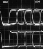
Here's a scope shot of a Neweva (taken from Jim Hagerman) which still shows ringing. Top pic is a bad trafo, bottom is neweva.
Edit: Oh & another problem raised about this whole area - RF experts over on Diyhifi say that SPDIF cable should be longer than 2 meters on a properly terminated 75 ohm line (I think), shorter gives all sorts of cable reflection problems! I don't know if this is related to the trafo or not?
Both transformers were terminated in 75 ohms and then run through a 2nd order low pass filter, which slowed down the edges and added overshoot. The important thing to notice is the zero crossings
Edit: Oh & another problem raised about this whole area - RF experts over on Diyhifi say that SPDIF cable should be longer than 2 meters on a properly terminated 75 ohm line (I think), shorter gives all sorts of cable reflection problems! I don't know if this is related to the trafo or not?
Attachments
Last edited:
Most CD drives and players with SPDIF out do employ pulse transformers.
The PT is used of two reasons.
First of all it is often used as a step down transformer from the standardised ~3V to ~1V out.
Next it provides insulation and protection.
The downside of using PT´s is mainly hysteresis and thus jitter.
Hi All,
What kind of jitter are you talking about? Cycle-to-Cycle, Period, Phase?
Regards,
VS
Hi Guys, I am a newbie in this forum and also newbie in electrical/electronic knowledge. So some of you may find these questionnaire dummies compare to what you all have been debating about; but would be glad if you are patience enough to guide this fool
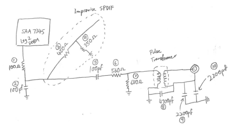
This is part of a circuit from Marantz CD63Ki as I have been toying with the direct tap into SPDIF circuit to get the purest signal out to DAC.
SPDIF Questions:
- SAA7345 datasheet showing output of leg 2 DOBM is 4.5 to 5v. But measure using digital multimeter through DC is 2.5v. Should I be measuring using AC instead?
- Consider all 5v of DOBM short to ground without any resistor or cap, regardless of equipment failure also, why the SAA7345 will not malfunction?
- Base on voltage divider calculation, I should be getting 1.944v from my Improvised SPDIF. Correct?
- If 1.944v achieved, does it mean it is slowly bleeding 3.1v to ground through No 4?
- If it is not 1.944v achieved, does it mean the rest of the circuit from No 5 onwards influence the changes?
- Is getting the 75ohm impedance important? Where value of No 4 is set to 75ohm? (The receiving chip on the DAC is DIR9001 can take a max 6.5v if not mistaken, also the coaxial lead from No 3 to )
- Is having the cap in series to block DC before No 3 important?
- Why is there no current leakage that I can feel from the Marantz player consider the main power input still uses the original 2 pin plug? Is there a resistive circuit in the player that “consume” all those voltage? (all the noise filter caps are short to ground).
Hi DF96, u r right, I don't fully understand. So help me out here.
I do understand the reflection when impedance isn't properly match. But I appreciate u can answer each of my question. That will be great.
The coaxial cable n bnc plug is 75 impedance. Now by shorting 350 ohm instead of 75 ohm. Is it acceptable?
I do understand the reflection when impedance isn't properly match. But I appreciate u can answer each of my question. That will be great.
The coaxial cable n bnc plug is 75 impedance. Now by shorting 350 ohm instead of 75 ohm. Is it acceptable?
Hi,
We can read at the beginning of the post than a cap would be better sometimes for sound quality than a pulse transformer for the DC stopping function.
What is the best according to you if the length is less than 20 cm between the spidf source and receiver with a BNC connectors and 75 ohms cable?
1) - Stopping the ground loop with a pulse transformer. Is there a minimum 1:1 pulse transformer quality to avoid the problems seen in the first posts ?
2) - Allow the ground loop with sharing the Gnd of the two pcbs (when it's possible) and only use a cap for security as DC blocker, because we can hear it (more details or bass resolution - see the first posts- ) against pulse transformer ?
If 2), I read than the maximum pulse fhz of a spidf signal is 6M hz : what sort of cap would you use ? The just enough band pass width you need for it or the fastest and stable like COG-NPO or polystyren?
A) smd or bulk ?
B) bulk X serie (military) COG ceramic 1uF - 5 mm between legs, plastic case
C) Polystyren bulk like 100 nf MIT for speaker crossover
D) Film : MKT,PEN, MKC, MKP
E) bypassing using A) to D)
Sorry if two cents, thanks
- Status
- This old topic is closed. If you want to reopen this topic, contact a moderator using the "Report Post" button.
- Home
- Source & Line
- Digital Line Level
- Pulse transformers SPDIF/AES-EBU