Lawrence Chan DAC Low pass filter
As pin 20 is a logic input (when CS8416 is in hardware mode) it does't really matter if it's wired to +5 or +3.3V via a 47k pull-up resistor. Logical high level is specified at 1.0V for the chip, low level is 0.5V.
It doesn't make any difference what so ever if you connect it to the regulator or to for instance pin 21 on the CS8416 chip (Logic Power). It is a pure digital signal so if the power on pin 21 is clean enough to work as Logic Power, it definetly is good enough to pull up a logical signal! So don't go out on a wild goose chase on this subject!
I have modified the LPF using the component values given by Crystal and I get the same clear high frequencies as without the filter caps, but with a very good filtering of frequencies above the audio band. This is the way to go, removing the filter completely may cause "undesirable side effects" if it's connected to an amplifier with a good power bandwidth. Frying your tweeters may be the only way to dicovere such an "undesirable side effect.."")
Removing all 1nF caps and leaving only C32 in place you will have a rather "soft" filter with it's -3DB point att 150kHz and only -5dB at 1MHz.
As pin 20 is a logic input (when CS8416 is in hardware mode) it does't really matter if it's wired to +5 or +3.3V via a 47k pull-up resistor. Logical high level is specified at 1.0V for the chip, low level is 0.5V.
It doesn't make any difference what so ever if you connect it to the regulator or to for instance pin 21 on the CS8416 chip (Logic Power). It is a pure digital signal so if the power on pin 21 is clean enough to work as Logic Power, it definetly is good enough to pull up a logical signal! So don't go out on a wild goose chase on this subject!
I have modified the LPF using the component values given by Crystal and I get the same clear high frequencies as without the filter caps, but with a very good filtering of frequencies above the audio band. This is the way to go, removing the filter completely may cause "undesirable side effects" if it's connected to an amplifier with a good power bandwidth. Frying your tweeters may be the only way to dicovere such an "undesirable side effect.."
Removing all 1nF caps and leaving only C32 in place you will have a rather "soft" filter with it's -3DB point att 150kHz and only -5dB at 1MHz.
CS8416 Mod
Forgive me for being so simple minded. I understand lots more about tubes than DACs. Could someone please post a close up of what is done to the CS8416 so I can understand what it should look like when I'm done?
Thank you all for your excellent posts. I am learning a lot and that's great stuff.
Best wishes to you all.
Ciao -- Mint
Drawing Program
Hi John,
A drawing of the mods would be great.
I've used Inkscape in the past. It's simple and free.
I hope it works for you.
http://www.inkscape.org/
Thanks very much.
Ciao -- Mint
Hi John,
A drawing of the mods would be great.
I've used Inkscape in the past. It's simple and free.
I hope it works for you.
http://www.inkscape.org/
Thanks very much.
Ciao -- Mint
Inkscape Tutorials
Hi John,
I forgot to include a youtube link that has a lot of tutorials that I found.
http://www.youtube.com/user/heathenxyt
Ciao -- Mint
Hi John,
I forgot to include a youtube link that has a lot of tutorials that I found.
http://www.youtube.com/user/heathenxyt
Ciao -- Mint
Ahh super will be even better to see photos, and perhaps over-lay the part no.s over each component?
I'm stuck at home suffering from M.E. so haven't gotten around to finishing my very crude layout using that software package yet. Your photos sound like a much better idea.
I'm stuck at home suffering from M.E. so haven't gotten around to finishing my very crude layout using that software package yet. Your photos sound like a much better idea.
Has anyone had any luck implementing the recommended filter values? I have the resistors on order and already have the caps so am looking forward to trying this out for myself. Just hope the parts are easy to desolder.
The DAC still sounds good - subjectively - to me as it stands however, with perhaps an ever so slightly lightweight midrange?
- John
The DAC still sounds good - subjectively - to me as it stands however, with perhaps an ever so slightly lightweight midrange?
- John
New filter components
Hi John,
I have successfully implemented all the changes to the filters, both the LPF and the C22, C23 and R2 filter. The sound is IMHO excellent, the somewhat aggressive high that I experienced without the 1nF filter caps is gone, as well as the, as you say, lightweight mids. I found the sound now to be very well balanced and really pleasant to listen to! The difference compared to my CD and DVD players is beyond my wildest expectations, specially concerning the "sound staging".
Since the PCB is multi layer (4 layers?) its is not very easy to remove the old components. Neither Solder Wick nor my desoldering "piston pump" made a good job of it, the holes are a bit too small leaving a too little gap between the pins asn the through plated hold. I had to heat one leg at the time while usingh a pair of pliers to retract the components one leg at a time from the component side. Some solder joints are really hard since they are connected to the power plane, thereby hard to heat sufficiently even if I use 50W Weller solder iron. But with a lot of patience I got them all out without damaging the PCB. Cleaning the holed was a process in it seld, I had to take smaller diameter copper wire and re-solder them in to the holes, only to use Solder Wich to remove the solder again. While heating the wire and slolder joint ai h´mamanged to get 8 of to holed cleared enough for mounting the new components.Some of the holes where impossible to get porperly cleane,capacitiors w
Hi Segran!
Thanks for your information and opinion on the sound of this DAC now you've implemented the changes. Sounds great!
So if I have this correctly - and to help others here - here are the changes needed so far:
R8, R9, R14, R15, R16, R17, R18, R19 = 13k7
R10, R11, R12, R13 = 3k32
C36,C37, C38, C39 = 1nF
C32, C33, C34, C35 = 220pF
C22 , C23 = ?
R2 = ?
LPF = ?
C27, C28, C30, C31 = Remove and insert wire link in place
Run wire diectly from output legs of op-amp to phono sockets.
If anyone could fill in the '?' and add any extra changes that would be fantastic.
Many thanks,
- John
LPF components
I understand you are preparing some images that will make the mods clear to anyone.
The first 4 lines listing components/values are quíte correct.
LPF is just short for Low Pass Filter which constitutes all the other R's and C's we've changed.
C6 and C54 may also be replaced by links/jumpers wires if you are really haunted by the "cap's-cause-distortion-bug" and confident that whatever amp you connect the DAC to has DC blocking on it's input. In fact, all the electrolytic cap's (C26, 27, 28, 29 ,30, 31 and C6, C54 form a high pass filter with a -3dB roll-off att 5 Hz. Removing these will extend the bass into infra sound regions. In my system though, it doesn't change the bass sonically.
I haven't removed the second OP yet since I'm contemplating the best way to do it. I want the mute relay still to work.
Right now I think I will remove the IC, R37,C55, R40, R4, C44 and R39 and solder wires from R23 and R38 to pin 1 and 7 of the IC socket on the solder side of the PCB.
I understand you are preparing some images that will make the mods clear to anyone.
The first 4 lines listing components/values are quíte correct.
C22 = 22nF, C23 = 1nFC22 , C23 = ?
R2 = 3kR2 = ?
LPF is just short for Low Pass Filter which constitutes all the other R's and C's we've changed.
C6 and C54 may also be replaced by links/jumpers wires if you are really haunted by the "cap's-cause-distortion-bug" and confident that whatever amp you connect the DAC to has DC blocking on it's input. In fact, all the electrolytic cap's (C26, 27, 28, 29 ,30, 31 and C6, C54 form a high pass filter with a -3dB roll-off att 5 Hz. Removing these will extend the bass into infra sound regions. In my system though, it doesn't change the bass sonically.
I haven't removed the second OP yet since I'm contemplating the best way to do it. I want the mute relay still to work.
Right now I think I will remove the IC, R37,C55, R40, R4, C44 and R39 and solder wires from R23 and R38 to pin 1 and 7 of the IC socket on the solder side of the PCB.
Hi
I'm the guy who published the direct coupling LM4562 in the lampizator web site.
The dac as is isn't flat with it's special equalization done by different RC combinaisons around the first op amp.
I tried to modify some parts around this op amp and ended to nothing.
You have the choice to leave it as is or completly redone the circuit arount this op amp.
The LM4562 is one of the best IF IT IS BROKEN IN. This means that it has to play at least 100 hours. The AD826 is better than a NE5534 but it has an annoying overbright high mid. The AD8066 with Browndog adaptors have slam and have terrific bass. They're not as natural sounding as LM4562. The OPA627 are too laid back.
I also tried tubes for output stage. This is good but believe me:
do you a favor:
Throw away your op amps, tubes, fets, Burson modules and use output transformers.
I used a pair of Lundahl LL1690 amorphous core and NOTHING beats this topology. It takes AT LEAST 100 + hours to be broken in but after that, you're in another league. Soundstage is huge, the image is wider, sound is mellower with better definition, it's the nirvana. It beats killer dacs.
Other things to do:
Replace the Sumlink pulse transformer for a Newava S22083 (Digi Key) They look the same but don't do the same sound.
Try a DIR9001 module to replace the CS8416 module. Replace the 3x100uF surface mount caps on the DIR9001 module with OS con Caps or good ones.
Replace the PLL parts value with the ones described here:
http://www.cirrus.com/en/pubs/errata/ER578D1.pdf
Have some fun with this marvelous dac
Here is the dac with the CS8416 receiver later changed for the
DIR9001
Attachments
![dac_lundahl_187[1].jpg](/community/data/attachments/135/135682-c9f2367952f99aee3da6151af26b8ddd.jpg)
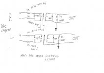
Because my writing on the drawing is bad, here are the parts for both channels
4 X 1K Mills non inductive wirewound
2 X 4,7 nF
2 X 40K (I used Rikens but other quality resistors can be ok)
2 X 7K Mills non inductive wirewound
2 X 400pF (mica or polypropylene but please no styroflex)
Price for the two Lundahls is $250 (US)
4 X 1K Mills non inductive wirewound
2 X 4,7 nF
2 X 40K (I used Rikens but other quality resistors can be ok)
2 X 7K Mills non inductive wirewound
2 X 400pF (mica or polypropylene but please no styroflex)
Price for the two Lundahls is $250 (US)
Edit .. this is the kit I was refering to
http://cgi.ebay.com/SAA7220-TDA1541...yZ122650QQssPageNameZWDVWQQrdZ1QQcmdZViewItem
http://cgi.ebay.com/SAA7220-TDA1541...yZ122650QQssPageNameZWDVWQQrdZ1QQcmdZViewItem
This measurement looks very similar to my testing of a Hong Kong DAC. But it's not the same one. That was for the smaller SMD board. You can see the modifications here http://www.jackenhack.com/blog/arch...7-dac-modified-to-work-as-it-should/#more-748. But I also ordered the "Big" DAC, but got a version with a DIR9001 chip instead of the CS8416. This means that they only can receive 96khz. But the good thing is that the DIR9001 has lower jitter value, and as an added bonus have the 24.576MHZ crystal located on the board which makes it really easy to change to a better clock.
this is the frequency response after taking out all that capacitors that drive HF to ground and leave only that 100 pico green capacitor that is in the opamp's feedback (in the schematic it is written that it has 56pF value but in reality it is 100pF - it might be changed also to 56pF - it is for the opamp not to oscillate)
An externally hosted image should be here but it was not working when we last tested it.
[/B]
- Home
- Source & Line
- Digital Line Level
- Experience with this DIY DAC ?