Deq
The DEQ2496 is much easier to mod with access to the dac outputs via the ribbon cable. It is also indispensible to have digital EQ in your system even if you use a stock DEQ digital in/ out into something like the big dac board.Hi All,
My cheap Chinese Ebay DAC has died and I am now considering a Behringer SRC2496. They are about $200 from Amazon. I have my UTC A-20 transformers and am wondering if anyone has any experience with this kind of combination. Do you have any advice?
Lastly, what is a good way to connecting the transformers to the DAC output? I have seen several approaches. I am no engineer but know how to solder and experiment.
Thanks and I hope all is well with you.
Ciao - Mush
Thanks Scott. I'll look into the DEQ2496.
Is there best way to connect the transformers with regard to load resistors and filtering? Do you know of a circuit to look at? I've gone through a lot of this thread and am not really sure how the DAC outputs need to be loaded.
Ciao
Is there best way to connect the transformers with regard to load resistors and filtering? Do you know of a circuit to look at? I've gone through a lot of this thread and am not really sure how the DAC outputs need to be loaded.
Ciao
No, the 1798 is completely different. It requires current to voltage conversion.
However, it's possible to use Monacors LTR110 (or almost any 1:1 trafos with center-tapped primaries) as a desimmetrization. One can put two conversion resistors on primary, or one conversion resistor on secondary. The trafos must be followed by gain stage, for example tube stage shown by me.
Hi All,
My cheap Chinese Ebay DAC has died and I am now considering a Behringer SRC2496. They are about $200 from Amazon. I have my UTC A-20 transformers and am wondering if anyone has any experience with this kind of combination. Do you have any advice?
Lastly, what is a good way to connecting the transformers to the DAC output? I have seen several approaches. I am no engineer but know how to solder and experiment.
Thanks and I hope all is well with you.
Ciao - Mush
I have one of these Behringers. No matter what have I done, it cannot even equal the performance of carefully modded CS4397 DAC. And PCM1798 DAC is even far better.
But the pcm1798 board in this dac
Upsampling 24bit/192 DAC mainboard ,USB, PCM1798 su eBay.it Processors, Home Audio, Electronics
have an I/V convertor, maybe is it possible to mount Monacors or other 1:1 trafo without modifications..
Upsampling 24bit/192 DAC mainboard ,USB, PCM1798 su eBay.it Processors, Home Audio, Electronics
have an I/V convertor, maybe is it possible to mount Monacors or other 1:1 trafo without modifications..
Caps
I still prefer to simply cap couple a single output to my amps. Review of the Jensen transformers to follow tomorrow when I get a chance to do some more critical listening.
Thanks Scott. I'll look into the DEQ2496.
Is there best way to connect the transformers with regard to load resistors and filtering? Do you know of a circuit to look at? I've gone through a lot of this thread and am not really sure how the DAC outputs need to be loaded.
Ciao
I still prefer to simply cap couple a single output to my amps. Review of the Jensen transformers to follow tomorrow when I get a chance to do some more critical listening.
But the pcm1798 board in this dac
Upsampling 24bit/192 DAC mainboard ,USB, PCM1798 su eBay.it Processors, Home Audio, Electronics
have an I/V convertor, maybe is it possible to mount Monacors or other 1:1 trafo without modifications..
Yes, it's possible, but is it optimal? I/V convertor on this board is op-amp based. Me myself dislike solutions like this.
In my present sound system there's no single semiconductor in the analogue signal path. Tubes only. Triodes only. All single ended. And the sound quality is to die for.
Thanks Scott. I'll look into the DEQ2496.
Is there best way to connect the transformers with regard to load resistors and filtering? Do you know of a circuit to look at? I've gone through a lot of this thread and am not really sure how the DAC outputs need to be loaded.
Ciao
As with many things, it is a bit more complicated.
First, there are two "kinds" of DACs: Voltage out and Current out. The Behringer that was suggested uses a AKM DAC which is a "voltage DAC".
Using that AKM as an example, the + and - legs (it is a balanced out) are riding on a DC. If you are using this as single-ended (a pre-amp with an RCA connector) then you must get rid of the DC. This can be done with capacitors to block the DC or can be done by a transformer (the voltages out are equal and only differ in sign).
The next issue is filtering (anti-aliasing). Part of this may be done by the DAC chip already (this is true of the AKM, but the filtering is insuffiecent). A transformer may provide additional low-pass filtering (or it may not).
The remaining issue is whether the DAC needs to see some series resistance (the AKM specs a 600 ohm or greater requirement). If this is not done then the pre-amp amy try to "draw power or current" from the DAC. They were not designed for that and the series resistance is required. In addition, the transformer may need to be loaded on the secondary side (it may or may not). If this is not done there may be some "ringing" and Bill has posted extensively on this.
So you need to consider the following: 1) is the DAC a voltage or current design, 2) does the DAC provide suffiecient low pass filtering, 3) does the transformer provide any low pass filtering, 4) is the gain sufficient - else you may need a step up transformer and the impedance reflected will correspondingly change), 5) are you using the transformer to cancel DC and convert from balanced to unbalanced. 6) is there a pre-amp? (or are you using this to "drive the cable" to the amp). Ther are others, but these are potentially major headaches.
Until these issues are specified, I would take any advice as being incomplete.
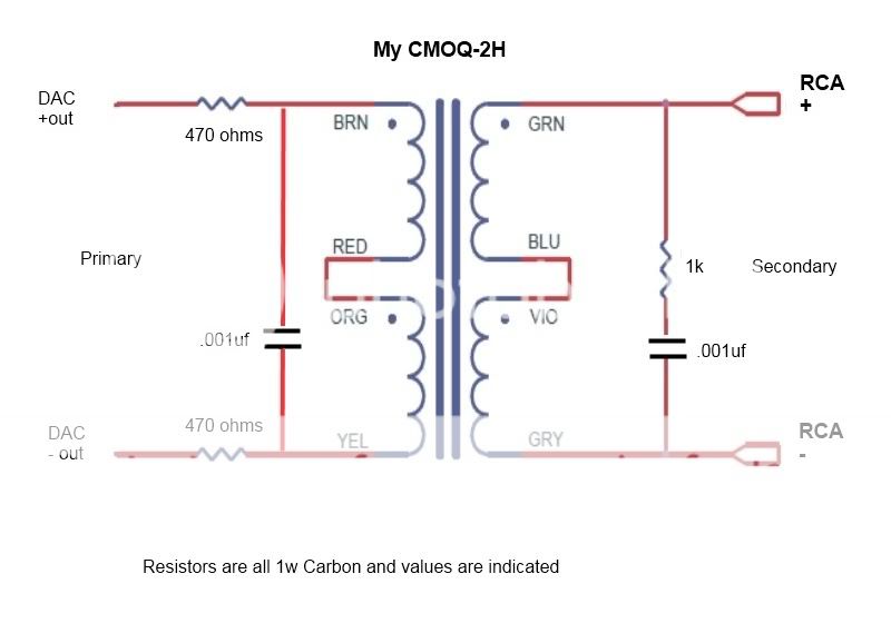
Thanks for your reply. My old DAC used the CS4398. I had it connected to the UTC A-20s via a resistor per each leg. I used r/c in series and a load resistor across the secondary. It sounded great. After one of the channels blew up, I began to wonder if the values and general network of loads and filters that I used werr at fault.
I am looking for suggestions for a circuit of resistors and capacitors for a voltage DAC connected via transformers could provide good performance and reliability. (I drive a 32 yr old Volvo, reliability is a big deal for me).
Thanks very much for your help.
I am looking for suggestions for a circuit of resistors and capacitors for a voltage DAC connected via transformers could provide good performance and reliability. (I drive a 32 yr old Volvo, reliability is a big deal for me).
Thanks very much for your help.
I haven't seen complete specs on the A20s but generally, output trafos have an unloaded impedance of around 100k or higher.
Voltage out dac chips don't want to see any load,they are voltage sources.
The A20s don't need a load to operate correctly, but filtering with RC circuits is pretty much mandatory for some dac chips. The A20s have limited bandwidth so they supply some filtering themselves, but a filter around 150khz wouldn't hurt anything and could possibly eliminate any ringing. The only sure way to tell is with a sig gen and a scope.
Primary series resistors should be around 250 to 500, depends on the chip. 4398 is OK with 250, others might want 500 depending on source resistance of the dac chip. They act as current limiters at the cutoff frequencies to protect the chip from over current. They also affect the low end cutoff F3 so it is a balancing act.
If you have the upsampling model, possibly the upsampling chip roasted due to the improper voltage on the daughter board. It's been reported by a few people.
Last edited:
Another old unit to try would be the Altec/Peerless 15356, they pop up on Ebay all the time.
Any suggestion on how to use these ones? It'll help a lot
I just found the specs on the 15356A again. Just google the number, it was the first link for me.
They do have a resonance frequency of 196khz so the filter is definitely in order, but an actual load is not required. 600 ohms is the secondary load used in testing to meet specs but generally the less secondary load they see the better they perform.
They do have a resonance frequency of 196khz so the filter is definitely in order, but an actual load is not required. 600 ohms is the secondary load used in testing to meet specs but generally the less secondary load they see the better they perform.
Bill, thank you very much for the heads up on the Altec's. I have my eye on a couple as we speak. You are a wonder, an absolute goldmine of info.
In many way's this thread is still alive because of you. For those of you new to the thread, Bill has been patiently helping simpleton's like me the whole distance. His advice can be pretty much taken as the gospel...
Keep up the good work Bill, your help is always appreciated.
Cheers
Rich
In many way's this thread is still alive because of you. For those of you new to the thread, Bill has been patiently helping simpleton's like me the whole distance. His advice can be pretty much taken as the gospel...
Keep up the good work Bill, your help is always appreciated.
Cheers
Rich
Thanks everyone. That circuit is pretty much what I had on my CS4398 DAC. I now have to figure out why the left channel stopped working.
So the consensus is that that CS4397 is better that the Behringer? I guess I'll stick with Cirrus.
Ciao and I hope you all are well -- M
So the consensus is that that CS4397 is better that the Behringer? I guess I'll stick with Cirrus.
Ciao and I hope you all are well -- M
Electrolytics?
Got my big dac board today. looking for the first place to grab the analog from the dac chip for a direct out mod since he didn't include a schematic or even a doc for the use of the switches on the dac chip board. flip the module over and see the labels L-, L+, R+, R-. Handy. Look at what they are connected to. Electrolytic caps for coupling, are you kidding me! All the money they put into the components and they couldn't come up with something better than that!? Out they come.
Got my big dac board today. looking for the first place to grab the analog from the dac chip for a direct out mod since he didn't include a schematic or even a doc for the use of the switches on the dac chip board. flip the module over and see the labels L-, L+, R+, R-. Handy. Look at what they are connected to. Electrolytic caps for coupling, are you kidding me! All the money they put into the components and they couldn't come up with something better than that!? Out they come.
i am listening to my stock dac that just came in the mail today, and i must say, i am not impressed at all. in fact, I'm rather disappointed. i got the 1798+9001 version and feeding through the optical, there's a definite listening fatigue, skinny bass, and just not that musical as i expected. I wanna put the blame on the cheap Chinese transformer that came with it- it's tiny and it hums. it's also coupled with a digital filter that i remember reading that it's useless? please correct me if i'm wrong as i'm ready to gut it out. as for the listening fatigue, the top end is definitely screechy and doesn't slowly roll off as my previous lite dac 60 that my ears are used to. the imaging and the soundstage is very realistic, though, and there's loads of detail. these impressions are from using the stock op-amp NE5532. what should my next upgrade be in order to soften the top end against the listening fatigue? bigger tranny or 'dark' sounding op-amp? i'm tight on the budget so the output trafos will have to wait...
- Home
- Source & Line
- Digital Line Level
- Experience with this DIY DAC ?