Hi,
Sounds like a nice project - That amp / preamp combo will be HUGE though.(In keeping with many other projects I suppose).
I was trying to cram too much into this case at first (7 Sympatico modules plus toroidal AND DSP!), but after the positive comments about "Class-D" type amps like the Sure amp, I moved over to class-D and I now have a lot more room in the case.
(I'm planning to stack another Sure amp on top of this one if I can ever get the rest of the details sorted).
btw, does anyone know of a cheap I/V stage suitable for the Sabre chip? Would something like a modified IVY III type circuit work OK (if only single-ended outputs were needed)?...
This would save a fair bit in the cost as I would then only need eight OPA1632's and four LME49720's.
OzOnE.
Inside the Preamp all the stages are going to be separated by 1/16 copper sheets to reduce noise and crosstalk between sections.
Power supply will be buried at the bottom of the case and will be separated from the modules as well to reduce EMI with 1/8 thick copper.
As far as the back panel, i will have another one made to the exact dimensions as the one that came plus the holes required for the connectors.
I just have to figure how to machine out the front panel for the controls and mounting of the LCD display.
The problem I'm having now is that the Sabre locks onto the I2S audio from the DSP perfectly fine when using an optical input from a DVD player, but...
...If I use the optical output from the PC (tried two different sound cards), the Sabre locks on and plays audio for three seconds, then it looses lock for one second and the process repeats?
The sound cards work perfectly through optical to a commercial amp (even through a very cheap 5 metre optical cable). I tried three different cables with the Sabre DAC and I still have this "lock" problem?
The decoded I2S signals from the DSP board look identical on the scope whether I'm using the DVD player optical output (audio fine), or PC optical output (audio intermittent)?
May I make them sure that;
0. Your Sabre chip is ES9018.
1. You are using sampling rate 48 kHz and data length 16 bit inputs from both your DVD-player and PC interface and does your Denon DSP module output fs=48 kHz and BIT CLOCK = 64 * fs ( 64= 32 * 2 ) for the both DVD-player and PC interface cases?
2. Are those waveforms of BIT CLOCKs and WORD CLOCKs for the both cases almost identical? How are the timings between BIT CLOCK and WORD CLOCK? Are they almost identical either?
I don't think you use BIT CLOCK = 32 * fs ( 32 = 16 * 2) for the PC interface case. However, I just remember that ES9018 only supports BIT CLOCK = 64 * fs.
Hi, Bunpei,
I'm using the ES9008 ("24-bit" version).
All digital audio signals are passed through the DSP board. The sources are standard S/PDIF, so should be 64fs (32-bits per Left / Right, but only 16, 18, 20, or 24 bits actually used for audio).
The thing is, it's working fine when using coax from the PC instead of optical? The signal format from coax and optical should be identical (apart from slight bias / jitter differences etc.)
I've been too busy to try changing the resistors on the I2S lines to match the impedances etc. I'm sure this is the main problem, so I'll fix it soon. I can always use coax for the time being, it's just that my on-board sound card (coax) sounds dreadful.
I'm not sure that this amp will ever get finished. It basically just needs a cheap 8-channel I/V stage and a 7-channel speaker protection relay board to finish it off.
I also have a very nice FriendlyArm board and 3'5" LCD which I'm planning to fit to the front of the amp chassis to do basic control and possibly generate some test signals. It's way overkill though, and difficult enough just to get simple I2C working and deciding on an OS to use.
Thanks for everyone's help though, I think I'll put the optical / coax thing to rest for now.
OzOnE.
I'm using the ES9008 ("24-bit" version).
All digital audio signals are passed through the DSP board. The sources are standard S/PDIF, so should be 64fs (32-bits per Left / Right, but only 16, 18, 20, or 24 bits actually used for audio).
The thing is, it's working fine when using coax from the PC instead of optical? The signal format from coax and optical should be identical (apart from slight bias / jitter differences etc.)
I've been too busy to try changing the resistors on the I2S lines to match the impedances etc. I'm sure this is the main problem, so I'll fix it soon. I can always use coax for the time being, it's just that my on-board sound card (coax) sounds dreadful.
I'm not sure that this amp will ever get finished.
It basically just needs a cheap 8-channel I/V stage and a 7-channel speaker protection relay board to finish it off.I also have a very nice FriendlyArm board and 3'5" LCD which I'm planning to fit to the front of the amp chassis to do basic control and possibly generate some test signals. It's way overkill though, and difficult enough just to get simple I2C working and deciding on an OS to use.
Thanks for everyone's help though, I think I'll put the optical / coax thing to rest for now.
OzOnE.
Lots of information here about it but I don't know where you buy it from.
Test hearing of Evaluation boad of ES9008S ESS Technology
Test hearing of Evaluation boad of ES9008S ESS Technology
i2c with arduino
just started playing with my arduino Duemilanove (I’m newbie with it).
sadly I cannot get the volume control via I2c running with my buffalo 1.
I known that is not a arduino list, but maybe I'm making here a stupid fundamental error. I'm using the wire lib.
A few questions:
about wiring from arduino to buffalo:
pin 4 to sda
pin 5 to scl
connect grounds.
Is it needed to connect Vdd on the buffalo too -- and do we need pull up resistors (I don't think so as the pull up res are in the buffalo 1 already ) ?
after that I tried the following test program to attenuate the vol.
but nothing happens — but the ‘build in LED’ from the arduino is flashing.
from the data sheet I2C addr. is 0x90 (addr pin is open). but what are the register addr starting from 1 to 8 ? (see page 9). (what means (default = 8’d0 - is that 8bit digital 0 ??).
it was strange that the datasheet was not on the ess website. google gives 202 results of the pdf...
thanks.
#include <Wire.h>
void setup()
{
Wire.begin(); // join i2c bus (address optional for master)
}
byte vol=0;
int ledPin = 13; // led on the arduino
void loop()
{
// Do stuff repeatedly
digitalWrite(ledPin, LOW);
delay(100);
Wire.beginTransmission(0x90); // Address of DAC is hex 90
Wire.send(0x01); // Address of register 1 is hex 1
Wire.send(vol); // Value into register vol
Wire.send(0x02); // Address of register 2 is hex 2
Wire.send(vol); // Value into register vol
Wire.send(0x03); // Address of register 3 is hex 3
Wire.send(vol); // Value into register vol
Wire.send(0x04); // Address of register 4 is hex4
Wire.send(vol); // Value into register vol
Wire.send(0x05); // Address of register 5 is hex 5
Wire.send(vol); // Value into register vol
Wire.send(0x06); // Address of register 6 is hex 6
Wire.send(vol); // Value into register vol
Wire.send(0x07); // Address of register 7 is hex 3
Wire.send(vol); // Value into register vol
Wire.send(0x08); // Address of register 8 is hex4
Wire.send(vol); // Value into register vol
Wire.endTransmission();
digitalWrite(ledPin, HIGH);
delay(100);
vol=vol+8; // steps to 0.5db each. max attenuation=-127db
if(vol == 255) // if reached 256th position (max)
{
vol = 0; // start over from 0db
}
}
I use the following:
#define SABRE_ADR 0x48 // I2C Hex address of the Sabre DAC
I have defined the following as references for my programming:
#define DEFAULTVOL 0x28 // -20 dB
#define MINVOL 0xc6 // -99dB - Dac adjustment is 0.5 db
#define MAXVOL 0x00 // -0 dB
#define DIMVOL 0xb4 // -90dB The volume level when dimming the volume
Then the code for increasing the volume by 0.5 dB are as follows
(As I stores all settings in EEPROM and reads back the stored values at powerup you can disregard the EEPROM programming):
// The following for volume up
case KEYVOLUP:
switch(volDimSTAT){
case 0:
if (currVol > MAXVOL) // Check if already at max numerical Volume
{
currVol=currVol-1; // Increase 0.5 dB
EEPROM.write(currVolAddr, currVol); // Write currVol value to EEPROM address
I2C_write(SABRE_ADR, 0x00, currVol); // Write new volume data (Register 0)
I2C_write(SABRE_ADR, 0x01, currVol); // Write new volume data (Register 1)
I2C_write(SABRE_ADR, 0x02, currVol); // Write new volume data (Register 2)
I2C_write(SABRE_ADR, 0x03, currVol); // Write new volume data (Register 3)
I2C_write(SABRE_ADR, 0x04, currVol); // Write new volume data (Register 4)
I2C_write(SABRE_ADR, 0x05, currVol); // Write new volume data (Register 5)
I2C_write(SABRE_ADR, 0x06, currVol); // Write new volume data (Register 6)
I2C_write(SABRE_ADR, 0x07, currVol); // Write new volume data (Register 7)
// setupSabre ();
delay(IRCdelay);
break;
}
break;
case 1:
break;
}
The code for decreasing the volume are as follows:
// The following for volume down
case KEYVOLDOWN:
switch(volDimSTAT){
case 0:
if (currVol < MINVOL) // Check if already at min Volume
{
currVol=currVol+1; // Decrease 0.5 dB
EEPROM.write(currVolAddr, currVol); // Write currVo value to EEPROM address
I2C_write(SABRE_ADR, 0x00, currVol); // Write new volume data (Register 0)
I2C_write(SABRE_ADR, 0x01, currVol); // Write new volume data (Register 1)
I2C_write(SABRE_ADR, 0x02, currVol); // Write new volume data (Register 2)
I2C_write(SABRE_ADR, 0x03, currVol); // Write new volume data (Register 3)
I2C_write(SABRE_ADR, 0x04, currVol); // Write new volume data (Register 4)
I2C_write(SABRE_ADR, 0x05, currVol); // Write new volume data (Register 5)
I2C_write(SABRE_ADR, 0x06, currVol); // Write new volume data (Register 6)
I2C_write(SABRE_ADR, 0x07, currVol); // Write new volume data (Register 7)
// setupSabre ();
delay(IRCdelay);
break;
}
break;
case 1:
break;
}
Last edited:
Good to see you using Arduino
If I remember correctly, the I2C address is put in 7 bits so rather than 0x90 it is 0x48 (as indicated by RayCTech above). The rest seems to be fine.
You also need to share the ground with Buffalo. And I think the Buffalo is 5V tolerant (When I programmed the OPUS, I used a 5V to 3.3V level converter because the Wolfson parts are not 5V tolerant)
You can see an implementation of the code here: MY PROJECTS
You can see more Arduino programming for TPA boards here: H I F I D U I N O
vol control arduino is working :-
thanks a lot for the examples)))))
without this help, I could not get it running.
the following small test prog sets the vol. .
next I'll try to implement a rotary encoder.
there is a nice lib for using the rotary encoder from old mechanical PS2 mouse.
Arduino playground - Ps2mouse
let's see
#include <Wire.h>
// Define register values, etc to facilitate programming
// Note: Reg address is address plus R/W bit
// This is why the address here is different from the
// address in the data sheet
#define REG0 0 // Register 0 address (Volume Adjustment)
#define REG1 1 // Register 1 address (Volume Adjustment)
#define REG2 2 // Register 2 address (Volume Adjustment)
#define REG3 3 // Register 3 address (Volume Adjustment)
#define REG4 4 // Register 4 address (Volume Adjustment)
#define REG5 5 // Register 5 address (Volume Adjustment)
#define REG6 6 // Register 6 address (Volume Adjustment)
#define REG7 7 // Register 7 address (Volume Adjustment)
#define MAXVOL 0 //-0 dB
#define DEFAULTVOL 100 //-50 dB this is 50x2=100
// The write to ESS9008 DAC routine
void bufwritereg(byte regaddr,byte regval)
{
Wire.beginTransmission(0x48);
Wire.send(regaddr);
Wire.send(regval);
Wire.endTransmission();
}
// set all register to same vol
void set_vol(byte regval)
{
bufwritereg(REG0,regval);
bufwritereg(REG1,regval);
bufwritereg(REG2,regval);
bufwritereg(REG3,regval);
bufwritereg(REG4,regval);
bufwritereg(REG5,regval);
bufwritereg(REG6,regval);
bufwritereg(REG7,regval);
}
// Declaring some more variables
byte ledPin = 13; // led on the arduino
byte regval=0; // variable for volume lower bits
void setup()
{
Wire.begin(); // join i2c bus (address optional for master)
}
void loop()
{
digitalWrite(ledPin, HIGH);
regval=MAXVOL;
set_vol(regval);
delay(5000);
digitalWrite(ledPin, LOW);
regval=40; // -20db
set_vol(regval);
delay(5000);
}
thanks a lot for the examples
))))) without this help, I could not get it running.
the following small test prog sets the vol. .
next I'll try to implement a rotary encoder.
there is a nice lib for using the rotary encoder from old mechanical PS2 mouse.
Arduino playground - Ps2mouse
let's see
#include <Wire.h>
// Define register values, etc to facilitate programming
// Note: Reg address is address plus R/W bit
// This is why the address here is different from the
// address in the data sheet
#define REG0 0 // Register 0 address (Volume Adjustment)
#define REG1 1 // Register 1 address (Volume Adjustment)
#define REG2 2 // Register 2 address (Volume Adjustment)
#define REG3 3 // Register 3 address (Volume Adjustment)
#define REG4 4 // Register 4 address (Volume Adjustment)
#define REG5 5 // Register 5 address (Volume Adjustment)
#define REG6 6 // Register 6 address (Volume Adjustment)
#define REG7 7 // Register 7 address (Volume Adjustment)
#define MAXVOL 0 //-0 dB
#define DEFAULTVOL 100 //-50 dB this is 50x2=100
// The write to ESS9008 DAC routine
void bufwritereg(byte regaddr,byte regval)
{
Wire.beginTransmission(0x48);
Wire.send(regaddr);
Wire.send(regval);
Wire.endTransmission();
}
// set all register to same vol
void set_vol(byte regval)
{
bufwritereg(REG0,regval);
bufwritereg(REG1,regval);
bufwritereg(REG2,regval);
bufwritereg(REG3,regval);
bufwritereg(REG4,regval);
bufwritereg(REG5,regval);
bufwritereg(REG6,regval);
bufwritereg(REG7,regval);
}
// Declaring some more variables
byte ledPin = 13; // led on the arduino
byte regval=0; // variable for volume lower bits
void setup()
{
Wire.begin(); // join i2c bus (address optional for master)
}
void loop()
{
digitalWrite(ledPin, HIGH);
regval=MAXVOL;
set_vol(regval);
delay(5000);
digitalWrite(ledPin, LOW);
regval=40; // -20db
set_vol(regval);
delay(5000);
}
Very nice.
For rotary encoder you can look at the following code: H I F I D U I N O: Arduino Code for Rotary Encoder
To keep the code simple (simple for me to understand) I added some capacitors to the rotary encoder to eliminate the mechanical glitches...
Also tried the mouse wheel... but liked the standard rotary encoder better...
For rotary encoder you can look at the following code: H I F I D U I N O: Arduino Code for Rotary Encoder
To keep the code simple (simple for me to understand
) I added some capacitors to the rotary encoder to eliminate the mechanical glitches...Also tried the mouse wheel... but liked the standard rotary encoder better...
Effect of master clock oscillator quality
Recently a Japanese manufacturer, Fidelix published an interesting report for the relationship between grades of master clock oscillators and measured purity results for a test signal.
ƒNƒ�ƒbƒN‚̃Wƒbƒ^�[‚Ì‘ª’è•û–@ (In Japanese)
They are now in the final development stage of their DAC product, CAPRICE, that uses ES9018 chip and they say their commercial product will be released within a month.
They tried three crystal oscillators of different grades on the CAPRICE board. Their frequencies were between 90 MHz and 100 MHz.
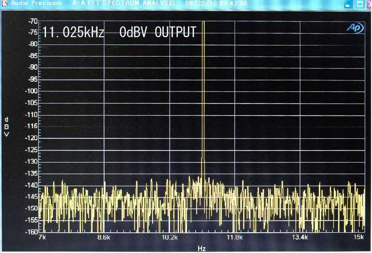
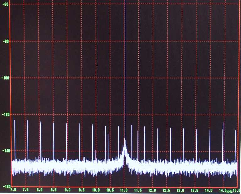
A test S/PDIF signal of pure 11.025 KHz generated by AP SYS2722 was injected to CAPRICE DAC and its analog output was measured with SYS2722.
Type 1. Fidelix proprietary crystal oscillator with an amplifier of bipolar devices. A DC power supplied for this oscillator comes from a proprietary regulating circuit. A crystal unit used in this oscillator was selected from several samples available in markets. The spectral measurement result shows a very sharp peak.
http://www.fidelix.jp/img/11.025kHz.jpg
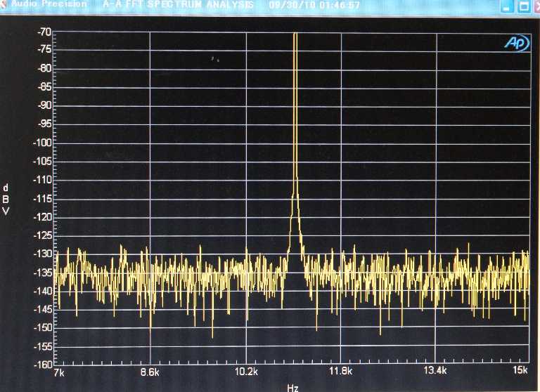
Type 2. A basic grade crystal oscillator easily available in Japanese markets (not special, not bad) The result shows an apparent peak broadening and a noise floor raise.
http://www.fidelix.jp/img/11.025kHzb.jpg
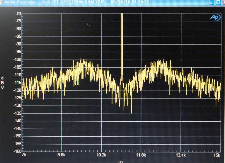
Type 3. A junk crystal oscillator
http://www.fidelix.jp/img/11.025kHzc.jpg
They say results in listening just match well the spectral purities measured.
Recently a Japanese manufacturer, Fidelix published an interesting report for the relationship between grades of master clock oscillators and measured purity results for a test signal.
ƒNƒ�ƒbƒN‚̃Wƒbƒ^�[‚Ì‘ª’è•û–@ (In Japanese)
They are now in the final development stage of their DAC product, CAPRICE, that uses ES9018 chip and they say their commercial product will be released within a month.
They tried three crystal oscillators of different grades on the CAPRICE board. Their frequencies were between 90 MHz and 100 MHz.
A test S/PDIF signal of pure 11.025 KHz generated by AP SYS2722 was injected to CAPRICE DAC and its analog output was measured with SYS2722.
Type 1. Fidelix proprietary crystal oscillator with an amplifier of bipolar devices. A DC power supplied for this oscillator comes from a proprietary regulating circuit. A crystal unit used in this oscillator was selected from several samples available in markets. The spectral measurement result shows a very sharp peak.
http://www.fidelix.jp/img/11.025kHz.jpg
Type 2. A basic grade crystal oscillator easily available in Japanese markets (not special, not bad) The result shows an apparent peak broadening and a noise floor raise.
http://www.fidelix.jp/img/11.025kHzb.jpg
Type 3. A junk crystal oscillator
http://www.fidelix.jp/img/11.025kHzc.jpg
They say results in listening just match well the spectral purities measured.
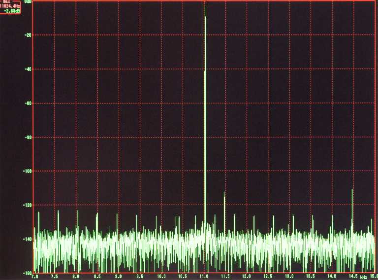
They added a new result measured by PC-based devices. They are surprised that a combination of an inexpensive audio signal input device and a free FFT analyzer program gives a similar result with that measured by an industry standard high level apparatus AP SYS2722. They used "E-MU 0404 Second Edition" sound card and FFT software, WaveSpecrta1.40, for 44.1 kHz analog output sampling.A test S/PDIF signal of pure 11.025 KHz generated by AP SYS2722 was injected to CAPRICE DAC and its analog output was measured with SYS2722.
http://www.fidelix.jp/img/E-MU.jpg
A J-Test signal WAV file was stored on a Audio CD disk and the file was played on an inexpensive CDP of Pioneer. ( its master clock was upgraded with Fidelix proprietary one)
It may be worth trying this method to compare your system with various and rich Stereophile measurement results without SYS2722.
The stereo J-Test signal of 16 bit version is available from here.
Bunpei, have you seen my email to you? you were trying to contact me while I was moving and had intermittent internet contact and no email, but we are ready for the clock if you are ready, both myself and acko have prepared for its arrival.
sorry for the OT guys, just noticed he posted in here not long ago
sorry for the OT guys, just noticed he posted in here not long ago
Is my understanding correct?
ES9018 is compatible for I2S of only 64fs bit clock. Namely, it does not accept 32fs bit clock even if the data is 16 bit length/channel and stereo.
Hi Bupei,
This is true, it must have a 64fs no matter what.
Dustin
Is my understanding correct?
ES9018 is compatible for I2S of only 64fs bit clock. Namely, it does not accept 32fs bit clock even if the data is 16 bit length/channel and stereo.
Hmmm...It seems by definition that if a DAC accepts 32 bit data (Sabre, Wolfson8741, other 32 bit DACs), BCK must run at 64fs. Even "low end" 24-bit DACs such as the PCM models require at least 48fs. Are there any current DACs that can run at 32fs bit clock?
I just know about ES9018 and WM8741....It seems by definition that if a DAC accepts 32 bit data (Sabre, Wolfson8741, other 32 bit DACs), BCK must run at 64fs. Even "low end" 24-bit DACs such as the PCM models require at least 48fs. Are there any current DACs that can run at 32fs bit clock?
In the case of WM8741 (it is 24 bit DAC), it detects whether BCLK frequency is 32*LRCLK or 64*LRCLK. If the BCLK frequency is 32*LRCLK, the DAC sets 16 bit mode automatically. Therefore, the DAC can accept I2S signals of a BCLK of 32*LRCLK.
I have once applied 192 kHz/32 bit I2S to WM8741 with BCLK of 64*fs. The DAC could play a normal sound. I suppose the DAC interprets the leading 24 bits and ignores residual 8 bits within the frame.
I have never experienced BCLK of 48*fs.
Last edited:
- Home
- Source & Line
- Digital Line Level
- ESS Sabre Reference DAC (8-channel)