Hi all,
I made some contributions in a projector thread about understanding the protocols for lamp ballast communication. This is a pretty great community. I'm not a sound engineer, so I might be wrong and looking for input.
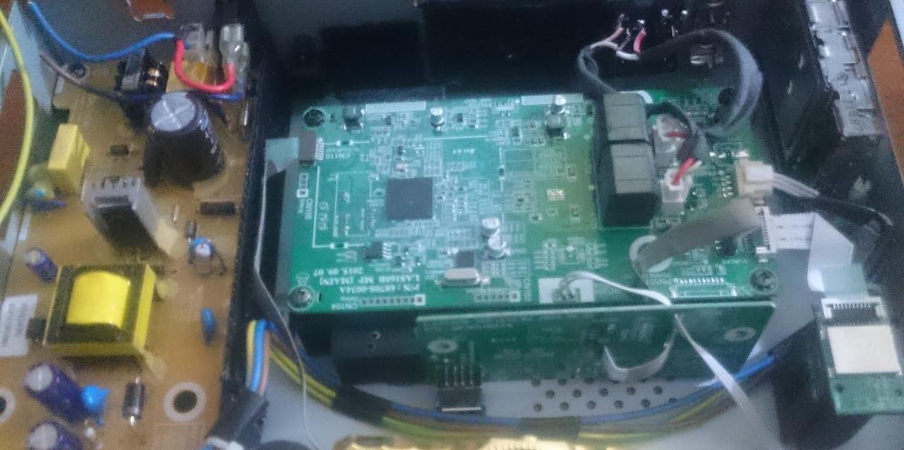
I am building an amp from the guts of a soundbar LG LAS160B.
This is going to be detailed, so please don't be deterred by the length of the post. There is a photo and the details are there to spare people's time.
https://postimg.cc/9w5HHqX6
Background:
I was not happy with the casing of my sound bar as it seemed to be deteriorating. So I salvaged the guts of it for use later. The sound used to reach about 85-89dB at max volume, subjectively from 3m away or 10ft indoors. Never really got loud enough to enjoy much and seriously lacking in bass and a lot of compression past 12kHz although I could hear some 14kHz come through.
I made some contributions in a projector thread about understanding the protocols for lamp ballast communication. This is a pretty great community. I'm not a sound engineer, so I might be wrong and looking for input.
I am building an amp from the guts of a soundbar LG LAS160B.
This is going to be detailed, so please don't be deterred by the length of the post. There is a photo and the details are there to spare people's time.
https://postimg.cc/9w5HHqX6
Background:
I was not happy with the casing of my sound bar as it seemed to be deteriorating. So I salvaged the guts of it for use later. The sound used to reach about 85-89dB at max volume, subjectively from 3m away or 10ft indoors. Never really got loud enough to enjoy much and seriously lacking in bass and a lot of compression past 12kHz although I could hear some 14kHz come through.
The old specs:
There was one rectangular "racetrack" full-range driver per channel in this 2.0 system 40mm x 100mm or 1 1/2" x 4". There were places for tweeters to go in and online tear-downs had tweeters, but mine came without any and there was nowhere to plug them in and no crossovers, although a lot of empty room in the driver compartments.
My thinking:
The first watt of power is the most important. I felt like LG did something amazing with their DSP and enclosure to manage to get the range they did out of these little speakers. I think the excursion was pretty high. I wanted to test my theory for myself and others. I play guitar a bit and close to a lot of musicians, so I kinda lamented the sound experience with TVs. Like we gave up on a century of speaker development to have these sleek bars. They sure look good and can be good if you get really expensive ones with a ton of engineering in them. But fighting against physics is hard. So my idea was to use some bookshelf speakers with the amplifier only of the sound bar and have the niceties of bluetooth when I'm lazy and optical in etc for permanent connections.
So I only need 1W of power to get 81 dB of sound right at 1m? Didn't feel like it at all. But I went with the stated numbers. 25W per channel of output power suggests about 14 dB of gain. This should bring up the volume to 95dB. Listening from 10 feet away drops this by say 9 dB but there was 3 dB of room gain, so a final 89dB. This is what I think I was hearing so I thought I could keep running with these numbers. So I just had to build it out into a nice chassis and choose some speakers to go with it was my hope.
New (to me) speakers:
Since this is a test setup, I wanted to try it on some speakers I'm not too attached to. I gave away my Panasonic SA-PM25 speakers years before, but they were pretty ok. Nvm. I found some cheap old Sony SS-CMD373 speakers x2 on eBay for the test. They were not damaged and the resistance matched the stated impedances. I know impedance and resistance are not the same thing.
Each one is/has:
Calculations:
So, for these new speakers with the LG Amp, the first watt should get me say 88dB at 1 m.
The gain of the amp should be 14dB as before at full volume, but scaled due to impedance difference.
Since the impedance scaling is a factor of 4 ohms / 6 ohms, the power into 6 ohms would now be 25 x 4/6 = 16.7W.
This is worth 12dB.
So at full volume at 1m distance, the volume should be 100dB.
Making adjustments for the 3m listening distance and room gain brings this to 94dB.
Did it work?
Sure it makes a sound. The bass was ridiculously high at low volume on the remote. I had to eq -12 dB on the bass band of 60-100Hz on my android eq. That and add about 4 dB to each of the other bands brought it close to balanced. So now I could turn up the volume. The LG remote has a range of 40 button presses from min to max. At about level 16 up from 0 the amp was going into an undocumented protection procedure and flashing a red light. Power cycling and reconnecting would solve it. This is where I started scratching my head. What was going on?
It feels like I'm not even getting past the first 1W of power!
Diagnostic:
So I am absolutely surprised why some kind of protection circuit is kicking in at 14 steps out of 40 on volume.
What could be happening?
Ohms law suggests that the current would be lower with a higher impedance.
With the original 4 ohm load per channel, I = 14.5 V / 4 ohms = 3.6A equivalent to 52W which is double the rated capacity. These speakers never clipped at max volume.
With the new speakers at 6 ohms per channel, I = 14.5 V / 6 ohms = 2.4 A equivalent to 34W which is also higher than the amp capacity.
The buck converter chip AP6503 has a 3.5A current limiter at which point it drops to 70% output to protect the amp chip. This seems to make sense. So it should never stop at 2.4 A with the new speakers. At worst the output should drop to 70%.
The amp chip is TAS5733L. Its a 4 channel digital input amp 10W per channel at 10% THD. LG combined two channels to make one left, and the remaining two to make right. This made it 20 W per channel. Then they upped the PSU voltage to 14.5 to get it to 25W which is accepted practice on the datasheet, up to a max of 16 V.
This chip locks out if the voltage sags to 5.4V. There is a decent input supply capacitor on the 14.5 V supply, and an unpopulated spot for another. I doubt the voltage could sag that much when the speakers are limiting power consumption to less than the original amount.
There is an Automatic Gain Limiter function I don't really know about.
Why am I hitting any limits at all? Is there something about load impedance I am missing after a week of obsessively reading about this?
I look forward to your ideas. Sometimes it's something obvious. Sometimes not.
There was one rectangular "racetrack" full-range driver per channel in this 2.0 system 40mm x 100mm or 1 1/2" x 4". There were places for tweeters to go in and online tear-downs had tweeters, but mine came without any and there was nowhere to plug them in and no crossovers, although a lot of empty room in the driver compartments.
- SPL: 81 dB
- Bass Reflex (but there were no ports for this or passive resonators)
- Impedance: 4 Ohms (actually this was measured off-state resistance but quoted as impedance)
- Unshielded.
- 25 + 25 W Amp.
- 14.5V SMPS at about 5A.
My thinking:
The first watt of power is the most important. I felt like LG did something amazing with their DSP and enclosure to manage to get the range they did out of these little speakers. I think the excursion was pretty high. I wanted to test my theory for myself and others. I play guitar a bit and close to a lot of musicians, so I kinda lamented the sound experience with TVs. Like we gave up on a century of speaker development to have these sleek bars. They sure look good and can be good if you get really expensive ones with a ton of engineering in them. But fighting against physics is hard. So my idea was to use some bookshelf speakers with the amplifier only of the sound bar and have the niceties of bluetooth when I'm lazy and optical in etc for permanent connections.
So I only need 1W of power to get 81 dB of sound right at 1m? Didn't feel like it at all. But I went with the stated numbers. 25W per channel of output power suggests about 14 dB of gain. This should bring up the volume to 95dB. Listening from 10 feet away drops this by say 9 dB but there was 3 dB of room gain, so a final 89dB. This is what I think I was hearing so I thought I could keep running with these numbers. So I just had to build it out into a nice chassis and choose some speakers to go with it was my hope.
New (to me) speakers:
Since this is a test setup, I wanted to try it on some speakers I'm not too attached to. I gave away my Panasonic SA-PM25 speakers years before, but they were pretty ok. Nvm. I found some cheap old Sony SS-CMD373 speakers x2 on eBay for the test. They were not damaged and the resistance matched the stated impedances. I know impedance and resistance are not the same thing.
Each one is/has:
- 5 1/4" Woofer
- 1" Tweeter
- Impedance: 6 ohms
- SPL: 91dB is my estimate based on comparing 3 driver specs of the same type and averaging. Crude, but not a bad starting guess. The Panasonic speakers I gave away had 86dB and were 1" smaller drivers. For the purpose of calculating I guess we could estimate it to be 88dB at the low end.
- Frequency response about 40 Hz - 20kHz comparing it by ear to other speakers I have. Maybe goes a little lower. My phone app SPL meter shows activity around 30Hz but low amplitude.
Calculations:
So, for these new speakers with the LG Amp, the first watt should get me say 88dB at 1 m.
The gain of the amp should be 14dB as before at full volume, but scaled due to impedance difference.
Since the impedance scaling is a factor of 4 ohms / 6 ohms, the power into 6 ohms would now be 25 x 4/6 = 16.7W.
This is worth 12dB.
So at full volume at 1m distance, the volume should be 100dB.
Making adjustments for the 3m listening distance and room gain brings this to 94dB.
Did it work?
Sure it makes a sound. The bass was ridiculously high at low volume on the remote. I had to eq -12 dB on the bass band of 60-100Hz on my android eq. That and add about 4 dB to each of the other bands brought it close to balanced. So now I could turn up the volume. The LG remote has a range of 40 button presses from min to max. At about level 16 up from 0 the amp was going into an undocumented protection procedure and flashing a red light. Power cycling and reconnecting would solve it. This is where I started scratching my head. What was going on?
It feels like I'm not even getting past the first 1W of power!
Diagnostic:
- I tried one speaker at a time with similar results.
- I tried 8 ohm speakers which could be turned up without hanging the amp. But low max volume.I checked and resoldered the cables.
- I added an aluminium heatsink to the DSP and a big one to the amp chip. Measured that most of the circuit board was 26 degrees C in a 24 degree C room (79 F in a 75 F room). The amp chip got to 56 C or 133 F.
- The system is passively cooled, with a lot of air vents and a steel case. The heatsink itself reached 25 C at the tips, so was more than enough and I used thermal paste and it was screwed down firmly to the chip.
- The voltage buck converter didn't get hotter than the PCB.
So I am absolutely surprised why some kind of protection circuit is kicking in at 14 steps out of 40 on volume.
What could be happening?
Ohms law suggests that the current would be lower with a higher impedance.
With the original 4 ohm load per channel, I = 14.5 V / 4 ohms = 3.6A equivalent to 52W which is double the rated capacity. These speakers never clipped at max volume.
With the new speakers at 6 ohms per channel, I = 14.5 V / 6 ohms = 2.4 A equivalent to 34W which is also higher than the amp capacity.
The buck converter chip AP6503 has a 3.5A current limiter at which point it drops to 70% output to protect the amp chip. This seems to make sense. So it should never stop at 2.4 A with the new speakers. At worst the output should drop to 70%.
The amp chip is TAS5733L. Its a 4 channel digital input amp 10W per channel at 10% THD. LG combined two channels to make one left, and the remaining two to make right. This made it 20 W per channel. Then they upped the PSU voltage to 14.5 to get it to 25W which is accepted practice on the datasheet, up to a max of 16 V.
This chip locks out if the voltage sags to 5.4V. There is a decent input supply capacitor on the 14.5 V supply, and an unpopulated spot for another. I doubt the voltage could sag that much when the speakers are limiting power consumption to less than the original amount.
There is an Automatic Gain Limiter function I don't really know about.
Why am I hitting any limits at all? Is there something about load impedance I am missing after a week of obsessively reading about this?
I look forward to your ideas. Sometimes it's something obvious. Sometimes not.
Hi Naresh,
that is a good point. I spent most of the time making the chassis and nearly all of the plastic parts were repurposed from old 3D prints from other projects.
I broke open my car's amp to see what chip it uses and the amp part of the circuit is very straightforward. I was tempted to just rip it out and make an amp. There certainly is a lot of info about this on this forum.
But I also wanted to keep some features like a remote control and bluetooth and optical in. The micro system that came with the Sony speakers only had 25W per channel also, so this seemed like a good fit.
From the theory I have been reading, it's all about wattage and impedances. So I naively thought I could just pair these up and most of the work was on the chassis. But these puzzles are where the time is spent. Circuit bending is fun too when it works.
The amp cuts out at this point in this video (link starts at the moment the amp shuts down): FUN?R?L ? FLØW?RS - ???? | New Account: https://www.youtube.com/c/SOULMA-ES - YouTube
So I don't know enough to pinpoint this.
What was the purpose or need to do this?
Because it's there. (George Mallory).
Because it's there. (George Mallory).
Thank you for saying that, that's why I do things.
Update to continue my progress
One word I was looking for was crest factor. It's hard to do a google search when the last time I heard the word was many years ago and forgot it. I read there can be a need for overhead of 20dB for movies and 6dB for music. I have been thinking about this, but it comes back to this amp having enough overhead before, but now it suddenly doesn't. And that was my most-listened to song recently, so it's a fair comparison.
This thread might not lead me to getting pointed in the right direction, but it might help others going down this path. I found a good post on hackaday about a sound bar. There are millions of sound bars out there, and lots of people who like modding tech.
@Naresh: if you look up at the title bar of your browser, you might notice this is a place for audio enthusiasts and the Construction Tips subforum is where people come to do things like this. Do you know where you are typing?
There artistic reasons for making something that looks and behaves how you want, like the sound from an instrument. There are engineering and scientific reasons to work on the electronics. It's educational. If money is such a great concern to you, you could save 2 rupees of your time from writing denigrating comments. We are here because we choose to be here. I make things because I choose to. Any one of us can buy an amp so why are we building them? Do you want to pollute every thread with these comments? It's hateful when you make assumptions about my profession, tools and skills. And gender. You don't know me.
A touchy female, then?
God gave us knowledge, and this has led us to communicate.
Like you said, many sound bars out there.
It is yours to do what you like, your time and money.
But always, read up, many of the ideas that occur to us may have done so to others long back.
And do catch up, if millions of sound bars have been sold, a few thousands may have been modified...and there me also be dud models in those, more prone to failure.
Learn from those experiences, then go right ahead.
Be unique, not part of the herd.
Update 2:
I decided to open up one of the speaker boxes, which was easy since the drivers were screwed in.
I had expected no crossovers in this unit, but there was a single capacitor for the tweeter. Like I said, I'm not a sound engineer. Anyway this means when I was measuring resistance from the speaker terminals, I was only measuring speaker resistance of the woofer.
This was 5.5 ohms taking account of the resistance of my meter leads. The tweeter was 6 ohms.
Since they are in parallel, the load seen by the amp is 2.87 ohms! This is quite low for a simple amp and impedance is close to DC resistance at around 100Hz.
Thus when I play that song at that point, there is a drop to a low bass frequency. Impedance can even drop more at low bass notes. So this would give a spike in current causing a lockout of the amp chip and the buck converter. At 1.7A.
I mentioned the overhead needed being between 6dB for music and 20dB for movies. This song needs quite a bit of overhead. I'm assuming 10dB for now.
This leads to the following insights which are new to me. At 25W per channel, since two drivers are in each box in parallel, of nearly equal resistance, each gets a max of 12.5W.
This is equivalent to about 10dB.
So, when the bass drops, I need that 10dB of gain to handle it.
At the volume set to 14 steps of 40, perhaps I am only getting 1W out.
The bass goes low and eats my overhead and the protection circuit cuts off the amp.
On other songs I can play them louder, more vocal-oriented songs mostly in the mids.
So overhead was my problem. I can more precisely test this by doing an "impedance sweep".
This informs me what amplifier power and characteristics I need whether I want to build or buy. It does depend on the media you want to consume or create.
So I could bi amp each channel if I want and put some crossovers in my boxes.
I think this was a cheap and fast way of getting a start in this hobby. A little experimentation goes a long way.
- Home
- Design & Build
- Construction Tips
- Sound Bar Hacks and case mods