This a guide on how to attach your heatsinks to achieve 10-20% more efficiency without changing the design.
Is this necessary? In most cases, probably not. However keeping your amp cool is always a good thing and ultimately translates into better reliability.
One thing you should be aware of is that this process will make it hard to pull everything apart again. There is no thermal epoxy involved, but the "suction" effect is so strong that I've ripped chips from their sockets trying to get them apart. If you do have to remove them, remember to use a slow lateral motion before you pull on them.
Wet Sanding
On both the heatsink and the transistor there are imperfections as well as oxidation that impede thermal transfer. This is especially true with older transistors.
 (large)
Attach some NEW 800-grit wet/dry sandpaper to a sanding block. If you don't have a block then white-glue the sandpaper to some masonite. It works as well, if not better than a block.

For the heatsink, use copious amounts of water and gently sand back and forth with the metal grains. The mill marks will be inline with the metal grains. Deviating from this method will cause score lines the metal that will take twice as much work to sand out.
Sand with 800-grit until the surface "breaks". You'll feel the surface break when the block no longer sticks to the surface when you stop, but instead glides back and forth easily. Repeat the process for 2000-grit. The surface will break just like the 800-grit. Clean the surface with rubbing alcohol. Note that you'll never get a mirror finish with milled aluminum.
For the transistors, flip the sanding block upside down and add a very small amount of water. It's better to keep adding a few drops of water rather than submerging the transistor. The water shouldn't harm it in either case as long as you clean it with rubbing alcohol afterward. Move the transistor in a circular motion over the block with your fingertips. If you're OCD then use a figure-eight motion. Don't go overboard here. There will be a natural dip in the metal surface that can't be completely removed without potentially damaging the component. 50% flat is still 50% flatter than it was before.
Don't worry about removing the nickel plating. The surface will be sealed.
 (large)
You should now have perfectly flat surfaces
 (large)
Thermal grease/paste
Next, add a 3mm dab of thermal paste to the transistor. Less is more because we want the thinnest layer possible to cover the whole surface. I mean like microns thick! You can add more if it doesn't fully cover the surface. If there is one area that just won't cover then the surface is not flat enough and you may choose to go back and do more sanding.
As for brand, I have arctic silver but it really doesn't matter that much. The only thing I would say is that mil spec is more durable but also too thick to get a precision thermal layer.
 (large)
Now, I use a razor blade between my thumb and middle-finger, using my index finger for stability and to prevent the blade from flexing. I generally hold the transistor in my left hand but I had to put it down to take the picture.
 (large)
Important: Once you've spread the paste in every direction, then you must go over the entire surface in the same direction for 5-10 swipes. This is akin to cracking clay, in that you're aligning the paste particles so they fit together perfectly.
 (large)
Next, clean the mica sheet with alcohol and place it on the paste. Turn it over and press it on a surface. You can use your fingers but remember to clean the top of the mica with alcohol again.

For the second layer of paste, it's much easier to apply it to the heatsink but you waste more thermal paste. Adding it to the mica can be tricky because the layers like to slide around and you have to repeat the "cracking" process which pushes the mica in one direction.
 (large)
Finally, carefully lay the transistor down on the heatsink, imagining where the holes should line up. I can usually finesse all the layers into alignment with the screw. Rather than cranking the screw down and risking cracking the die, just snug the screw down while holding everything in alignment. Wait awhile for the layers to compress and then snug it down again.
If you care what it looks like, then clean then excess paste away with rubbing alcohol.
 (large)
Part 2 (passive convection) to be continued...
Is this necessary? In most cases, probably not. However keeping your amp cool is always a good thing and ultimately translates into better reliability.
One thing you should be aware of is that this process will make it hard to pull everything apart again. There is no thermal epoxy involved, but the "suction" effect is so strong that I've ripped chips from their sockets trying to get them apart. If you do have to remove them, remember to use a slow lateral motion before you pull on them.
Wet Sanding
On both the heatsink and the transistor there are imperfections as well as oxidation that impede thermal transfer. This is especially true with older transistors.
Attach some NEW 800-grit wet/dry sandpaper to a sanding block. If you don't have a block then white-glue the sandpaper to some masonite. It works as well, if not better than a block.
For the heatsink, use copious amounts of water and gently sand back and forth with the metal grains. The mill marks will be inline with the metal grains. Deviating from this method will cause score lines the metal that will take twice as much work to sand out.
Sand with 800-grit until the surface "breaks". You'll feel the surface break when the block no longer sticks to the surface when you stop, but instead glides back and forth easily. Repeat the process for 2000-grit. The surface will break just like the 800-grit. Clean the surface with rubbing alcohol. Note that you'll never get a mirror finish with milled aluminum.
For the transistors, flip the sanding block upside down and add a very small amount of water. It's better to keep adding a few drops of water rather than submerging the transistor. The water shouldn't harm it in either case as long as you clean it with rubbing alcohol afterward. Move the transistor in a circular motion over the block with your fingertips. If you're OCD then use a figure-eight motion. Don't go overboard here. There will be a natural dip in the metal surface that can't be completely removed without potentially damaging the component. 50% flat is still 50% flatter than it was before.
Don't worry about removing the nickel plating. The surface will be sealed.
You should now have perfectly flat surfaces
Thermal grease/paste
Next, add a 3mm dab of thermal paste to the transistor. Less is more because we want the thinnest layer possible to cover the whole surface. I mean like microns thick! You can add more if it doesn't fully cover the surface. If there is one area that just won't cover then the surface is not flat enough and you may choose to go back and do more sanding.
As for brand, I have arctic silver but it really doesn't matter that much. The only thing I would say is that mil spec is more durable but also too thick to get a precision thermal layer.
Now, I use a razor blade between my thumb and middle-finger, using my index finger for stability and to prevent the blade from flexing. I generally hold the transistor in my left hand but I had to put it down to take the picture.
Important: Once you've spread the paste in every direction, then you must go over the entire surface in the same direction for 5-10 swipes. This is akin to cracking clay, in that you're aligning the paste particles so they fit together perfectly.
Next, clean the mica sheet with alcohol and place it on the paste. Turn it over and press it on a surface. You can use your fingers but remember to clean the top of the mica with alcohol again.
For the second layer of paste, it's much easier to apply it to the heatsink but you waste more thermal paste. Adding it to the mica can be tricky because the layers like to slide around and you have to repeat the "cracking" process which pushes the mica in one direction.
Finally, carefully lay the transistor down on the heatsink, imagining where the holes should line up. I can usually finesse all the layers into alignment with the screw. Rather than cranking the screw down and risking cracking the die, just snug the screw down while holding everything in alignment. Wait awhile for the layers to compress and then snug it down again.
If you care what it looks like, then clean then excess paste away with rubbing alcohol.
Part 2 (passive convection) to be continued...
Last edited:
PPR To save my Screencast bandwidth I had attached the images and then referenced them in my post. I added links to larger images.
Yes glass is often used for flat sanding, but in my 20+ years of experience doing this (I started with Pentium II cartridges), the patience in the process is more important than the surface. Masonite is fine, and having glass that can allow the sandpaper slip around causes rocking and other opportunities for mistakes. Ultimately whatever you have that's flat is fine.
Yes glass is often used for flat sanding, but in my 20+ years of experience doing this (I started with Pentium II cartridges), the patience in the process is more important than the surface. Masonite is fine, and having glass that can allow the sandpaper slip around causes rocking and other opportunities for mistakes. Ultimately whatever you have that's flat is fine.
Great suggestions! TYTY
Hey kwadrofonik, thank you for posting this. Some thing along these lines is what I was thinking... for me, much like wet sanding / restoring car headlight lenses, on an older car... a very easy chore.
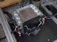
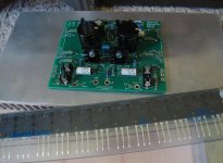
I am about to complete a few amp design / builds... have built and extensively tested my power supplies. Image 1. The next step is to attatch amplifier modules (Musical Concepts PA8 driver PCB, outputs and heatsinks) Image 2
I am using the dual die Exicon MOSFETS and want to maximize dissipation, with high'ish' bias setting / requirements, for 12 x 6 x 1.5 heatsink size... practical amp chassis sizes.
I am still on the fence between Sil Pads, or Mica / paste. Each having practical advantages. For me, the seemingly higher temperature gradient (25-30 degrees) between the output devices and the heatsink seem high with *green* Sil-Pads, leads me to question/concerns.
Hey kwadrofonik, thank you for posting this. Some thing along these lines is what I was thinking... for me, much like wet sanding / restoring car headlight lenses, on an older car... a very easy chore.
I am about to complete a few amp design / builds... have built and extensively tested my power supplies. Image 1. The next step is to attatch amplifier modules (Musical Concepts PA8 driver PCB, outputs and heatsinks) Image 2
I am using the dual die Exicon MOSFETS and want to maximize dissipation, with high'ish' bias setting / requirements, for 12 x 6 x 1.5 heatsink size... practical amp chassis sizes.
I am still on the fence between Sil Pads, or Mica / paste. Each having practical advantages. For me, the seemingly higher temperature gradient (25-30 degrees) between the output devices and the heatsink seem high with *green* Sil-Pads, leads me to question/concerns.
Attachments
Last edited:
I don't know what happened, but your image links do not work, even when Opened In New Window.
Have you tried just to hit that word LARGE ... that all it takes and it will open..
Cheers
Chris
yeah you can do this, and I think it will help to get better cooling.
There is another thing I might add here..
Stay away from these Rubber Pads.. Take MICA Washers.
I buy them in packages of 100pieces and them I slice them using a ART KNIFE in the middle, to get 4 Pieces out of one,, thickness 0.05mm
Use lots of UNICK Silicone Heatsink compound - you know the white smeary one..
If possible Sandwitch the Transistors, so these will disipate heat on both sides, and it promises outstanding performance.
All my heat sinks are leveled out by a CNC Machine, I do not like failing transistors because of heat..
For the transistor itself, I level them on a 5 mm thick Glasplate, the Sandpaper glued to the glas on their corners..
My NEXT Amp is all Passive Heatsinks.. Dimensions Lenght 400mm, width 75mm whereas the thickness of the surface where the transistors are mounted on is 10mm thick, then hight is 150mm
By the way these are sold as PASS AMP HEAT SINKS,,anyone can order them if the price don't matter.
So everyone out there happy sanding..
Regards Chris
Last edited by a moderator:
Very cool. Don´t find it so obsessive, rather done right.
We sand down lots of aluminium plates/carrier at work when they don´t have the needed flatness. Highly recommended at least for high power applications
So many DIYers underestimate flatness and thus good contact; instead using too much thermal grease (which, ideally, is only really there to fill "holes" in the surfaces).
I like the thin thermal foils and phase-change materials from Bergquist.
The foils are available in thicknesses below 100µm.
The phase-change materials are appropriate when you don´t have an even distributions of "holes" between your surfaces. Once the material hits 50° or so it becomes liquid and "adapts".
I am using the dual die Exicon MOSFETS and want to maximize dissipation, with high'ish' bias setting / requirements, for 12 x 6 x 1.5 heatsink size... practical amp chassis sizes.
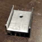
Hey that's a pretty cool concept. If it were me because I like to live on the edge, I wouldn't use insulators at all. The heatsinks are separate so they can be live. I would probably go with a finned U-channel heatsink design that you can flat sand down the middle.
IF I had to chose between thermal pads and the method above then hands down I'd go paste/mica/paste. The layers are so thin and perfectly connected that there is very little thermal resistance at all.
Also if you're daring like me then drill some small holes through the circuit board where those triangles are to allow air to flow through them.
Disclaimer: I'm far too pragmatic to be scared of board butchering and I'm willing to take the risk. To each their own.
hpro those were added after the fact.
Attachments
I like that idea myself but think more in terms of using "live" heat spreaders.If it were me because I like to live on the edge, I wouldn't use insulators at all.
So you have your (sanded or not) semiconductors on a flat aluminium plate (think 2"x2"x1/2" or whatever works/fits). This is live and is clamped (or so) onto the main heatsink with a thin thermal foil.
This could be useful when dissipation per device is "on the edge" or you are using unobtainium precious devices that have to survive a couple decades.
Last edited:
Have you tried just to hit that word LARGE ... that all it takes and it will open..
I know how to click. The post was re-edited after I commented.
This is live and is clamped (or so) onto the main heatsink with a thin thermal foil.
From a heat standpoint I think it would work well. My only thought about that is whether thermal foil is a weak dielectric. If so then you're essentially creating a capacitor against the collector of the transistor which is the output. The greater the surface area, the greater the capacitance. Capacitance on the output will create greater load and therefore more heat. Just something to think about.
Oh, yeah, good thinking! Easy to overlook when you only work on the "mechanical part" of the amplifier.My only thought about that is whether thermal foil is a weak dielectric. If so then you're essentially creating a capacitor against the collector of the transistor which is the output.
Probably [pF] but definitely to be considered.
Yes glass is often used for flat sanding, but in my 20+ years of experience doing this (I started with Pentium II cartridges), the patience in the process is more important than the surface. Masonite is fine, and having glass that can allow the sandpaper slip around causes rocking and other opportunities for mistakes. Ultimately whatever you have that's flat is fine.
A long time ago I was taught to do it without sandpaper straight on glass with abrasive powder and water. Also regularly turn the object and put pressure in the middle to avoid flattened sides.
That's a very good point in terms of metal-to-air conductance, but only if it's an extremely thin layer such as anodization and in the context of passive cooling because it promotes convection. There is another thread somewhere discussing black coatings.
For metal-to-metal, bare aluminum or copper is best. In fact both metals are stable because the surface readily oxidizes. Even that thin layer of oxidization can impede thermal transfer, so polishing the surface to bare metal before mounting the device is best.
For metal-to-metal, bare aluminum or copper is best. In fact both metals are stable because the surface readily oxidizes. Even that thin layer of oxidization can impede thermal transfer, so polishing the surface to bare metal before mounting the device is best.
black, white, red, anodized, they are all efficient emitters of far IR radiation compared to bare metal. The colour in the visible spectrum is not relevant.As you mention being obsessive, it's a known fact heatsinks coloured black radiate heat more efficiently than raw aluminum, little enough to raise the eyebrows.
I insist on using mica insulators as well, I found more equipment came into the shop with blown outputs seated on those stupid silicone pads.
However......
I find that all this "obsessiveness" over how a power transistor is mounted, and the "polishing" involved, is to me, silly babble.
It sure lives up to the "fanatics" in this site, but indeed aligns with obsessive compulsive behavior - and that's somewhat of a worry.
In all my decades of servicing equipment, I've yet to see an issue or problem arise from proper, but sensible installations of power devices.
Really
Polishing and so on will be useful only if you are at the limits of the design.
Simply use a 20% derating for dust and poor circulation, and another 20% for safety.
Nothing untoward will happen, and your equipment will be durable.
Mirror grade polishing of heat sinks! Really OCD, because the heat transfer compound is there for that reason, to remove air gaps and make the heat transfer more efficient.
Simple example:
You have a corner shelf for the amp, behind your console, away from circulation.
And another similar setup in the room center, under the air outlet.
The first set will have more issues dissipating the heat, and it is that worst case you have to design for, not some OCD guys who think aluminum is more costly than gold.
It is $3 per kilo here in heat sink sections...bigger heat sink is not going to break your bank.
Last edited:
- Home
- Design & Build
- Construction Tips
- Obsessive passive cooling guide