Hi friends
As I'm knee-deep into building stuff and want to get even deeper into, I started to experiment with various types of attenuators.
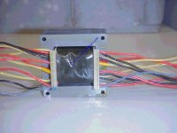
I couldn't resist the temptation and got myself 2 Autoformers to make an attenuator from it. The look very techy (not nifty/glossy/...), just 2 ugly, black-painted trannies with 24 wires (in groups of 3) coming out , but it came without further explanations.
Although I'm quite sure I'll get the needed assistance from the seller, I still wish to more or less understand how I'd do it.
If I was to find the order/sequence of the wires, how would I do it? Something like feeding it with a steady signal (like, x kHz 0.1V) and measuring which wire returns what?
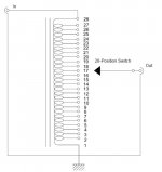
And how would I hook them up to the switch? The schematic according to acoustic dimension seems very simple and straight forward, so... it can't be too difficult. A 2-deck 24-points switch is what I need, is that correct?
BIG thank you
david
As I'm knee-deep into building stuff and want to get even deeper into, I started to experiment with various types of attenuators.
I couldn't resist the temptation and got myself 2 Autoformers to make an attenuator from it. The look very techy (not nifty/glossy/...), just 2 ugly, black-painted trannies with 24 wires (in groups of 3) coming out
, but it came without further explanations.Although I'm quite sure I'll get the needed assistance from the seller, I still wish to more or less understand how I'd do it.
If I was to find the order/sequence of the wires, how would I do it? Something like feeding it with a steady signal (like, x kHz 0.1V) and measuring which wire returns what?
And how would I hook them up to the switch? The schematic according to acoustic dimension seems very simple and straight forward, so... it can't be too difficult. A 2-deck 24-points switch is what I need, is that correct?
BIG thank you
david
Attachments
If you have a look on the website "askjanFirst.com" you'll see in the transformer section that your tva's are the STH20 items - just ask him for the wiring diagram - it'll save an enormous amount of stuffing around with a low resistance meter - they're just up the road from you and the phone is Telefon: (+49) 04882-6054551 - maybe just ring and ask.
He also lists a reasonable priced switch - the well known brands of multideck switches are quite expensive, much more than these transformers so maybe ask about these at the same time.
He also lists a reasonable priced switch - the well known brands of multideck switches are quite expensive, much more than these transformers so maybe ask about these at the same time.
here's little update:
After some confusion about the wires' sequence, i think I worked it out:
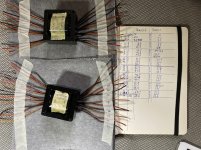
The green wires are first/last (in/"out"), and in-between it's B-R-Y ...
(in the left column, I had it Y-R-B and the wire-groups weren't in proper sequence.)
Next step: connecting the beast to the switch.
tips/hints welcome!
After some confusion about the wires' sequence, i think I worked it out:
The green wires are first/last (in/"out"), and in-between it's B-R-Y ...
(in the left column, I had it Y-R-B and the wire-groups weren't in proper sequence.)
Next step: connecting the beast to the switch.
tips/hints welcome!
Attachments
The wires will fit tightly but just fine...
I'll mount them next to the switch—one on the left, the other obviously on the right. They may have to get canned but I'll see to that later...
It's the wiring's logic that riddles me a bit:
At the switches first position ("muted") should be the last wire the highest resistance, right? (according to the schematic above)
But, do I just have to connect wire #23 to the switches input and the others in their corresponding position down to #1, ground the switch and connect the whole to the gain-stage?
OTOH, the schematic indicates (to me) that the last connection (#1 in the scm) should be grounded?
It would tremendously help if there'd be a pic of a built AVC...
Many thanks
david
PS
When I measured them wires, I got nice resistance increments of ~2 Ohms per step:
(Wire-colors: green R Y - B R Y - B R Y - B R Y - B R Y - B R Y - B R Y - B R green)
autoformer 1|autoformer 2
==========================
1.5|1.6
3.3|3.4
5.6|5.8
8.4|8.7
11.1|12.1
13.9|13.8
16.8|16.5
19.6|18.9
22.4|22.7
25.5|25.6
28.2|28.5
31.2|31.6
34.2|34.5
37.5|37.7
40.5|41.0
43.4|44.0
46.7|47.2
49.9|50.4
53.1|53.7
56.4|57.2
60.1|61.2
64.5|65.3
69.2|69.8
If you have a look on the website "askjanFirst.com" you'll see in the transformer section that your tva's are the STH20 items - just ask him for the wiring diagram - it'll save an enormous amount of stuffing around with a low resistance meter - they're just up the road from you and the phone is Telefon: (+49) 04882-6054551 - maybe just ring and ask.
He also lists a reasonable priced switch - the well known brands of multideck switches are quite expensive, much more than these transformers so maybe ask about these at the same time.
First post in this thread and straight to the right solution.
You mean, I got it right and don't believe it?…straight to the right solution.
that would be funny but difficult—I'd have to understand
Well I don't know what you mean but you bought 2 x autoformer STH20. No documentation was delivered. The seller should be able to deliver a wiring diagram with the product. So: just one email or one telephone call and you'd likely receive the wiring diagram which would have cost way less time.
Your systeem costs time AND it may introduce wiring errors which will again cost time. Eventually it will work and you will have understood what is there to understand but is it worth the extra trouble?
As jameshillj pointed out askjanfirst.com also sells the multideck 24 position switch for just 23,20 Euro. It is called TAT3929 and meant for operation with the STH20 autoformers. The site says:Rotary switch, four levels with23 positions ea. For use with our STH 20 volume control or with resistor ladders. Dimension help and pictures online for download
Last edited:
First post in this thread and straight to the right solution.
Well. It is a bit complicated. The seller isn't very obliging/helpful. (I had to tell him the wiring's "logic"...) I don't complain, Jan's cool and all, but I'm on my own on this one, and that's ok.
I just have to get through that all...
Complicated matters need to be made small to handle them. In this case a fellow German speaking DIYer could make the email or call.....
It‘s not a matter of language or distance.
It‘s more a matter of me being stubborn...
[emoji6]
Complicated matters need to be made small to...
Hei Jean-Paul
I followed your advice and contacted the seller. He‘s an engineer... but he admitted that he didn‘t really get it. (I wouldn‘t be surprised if that was just a pretext to have me going on with it...) which is what I’ll do as soon as I’m back ...
(Will meditate over the selector-switch in the meantime)
d
- Status
- This old topic is closed. If you want to reopen this topic, contact a moderator using the "Report Post" button.
- Home
- Design & Build
- Construction Tips
- Attenuators #1: Autoformer