I am totally ignorant of what I am doing. So I am wondering if someone knowledgeable could help (please). I am trying to decide on the layout of my tube amp.
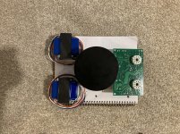
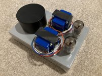
The paper notebook represents the outline of the chassis. The pcb and toroidal choke would be inside the chassis. The output transformers and the power transformer (with housing) would sit on top of the chassis. The same bolt would be used to mount the choke and power transformer to the chassis, though one is internal and one is external. Everything is banjo tight.
Are there any flaws here?
Attachments
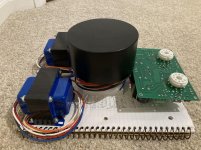
I could swap the OPTs position with the PT (PT in back and OPTs in the middle). If I did that, I would probably want to orient the OPTs with the bells facing each other--mostly to prevent different wires from crossing over each other. In this scenario, half of the board would be under the OPTs, albeit with 20 gauge steel separating them (OPTs on top of chassis, pcb inside chassis).
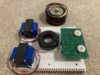
The chassis has a height of 3". The choke is 3.5" wide. There is no way to mount it vertically inside the chassis. I could mount the choke to the bottom cover of the chassis. That would put an 1.5" between the choke and the PT, with the 20 gauge steel separating them. If I did this, there also would an option to move the choke towards the OPTs/board, so it wouldn't be directly under the PT any longer.
The chassis has a height of 3". The choke is 3.5" wide. There is no way to mount it vertically inside the chassis. I could mount the choke to the bottom cover of the chassis. That would put an 1.5" between the choke and the PT, with the 20 gauge steel separating them. If I did this, there also would an option to move the choke towards the OPTs/board, so it wouldn't be directly under the PT any longer.
Last edited:
How set in stone is that size chassis? Another 1-1/2 inches each way, or 2 inches in one direction or the other would sure ease the strain.
The proposals in post #4 would work, especially allowing for a little overlap of the OPT and the PCB (each transformer 'casts a shadow' over its corner of the board). Then as you said, have the bells face each other across the chassis; slide the choke forward so it overlaps the PCB some, too.
Not sure about mounting it to the bottom cover, though. I think using standoffs to mount it to the same plane as the transformers might be better. That would also ease the wiring headache, too, even though it might reduce the spacing by an 1/8 of an inch or so.
Cheers, and Good Luck
The next size Hammond chassis is 16" x 8", instead of 12" x 8". That's a pretty big difference.
I am probably going to end up fixing the board to the bottom cover. 2 of the pcb mount holes will end up underneath the OPTs when vertically overlapped. Also, I would prefer not to have screws on top of chassis. Wiring becomes easier due to screw terminals.
Nothing can go underneath the board, the caps take up all of the real estate.
Here's a bizarre sideview depiction:
.....PTPTPT....OPTOPT..TU
.....PTPTPT....OPTOPT..BE
...CASECASECASECASECASE
...A....................BOARD...S
...S.........CHOKE BOARD...A
...EBOTTOMCOVERBOTTOMC
Last edited:
Mounting the choke directly below the power transformer may be a mistake. It could pick up some noise. Could you rotate the choke 90 degrees and mount it to the side of the case?
Usually there is no issue with mounting a filter choke right by the power transformer. The bigger problem usually comes when a choke gets mounted too close to an OPT or an input stage since chokes (being that they are large inductors with a lot of turns) can be very noisy.
Usually there is no issue with mounting a filter choke right by the power transformer. The bigger problem usually comes when a choke gets mounted too close to an OPT or an input stage since chokes (being that they are large inductors with a lot of turns) can be very noisy.
If I moved the choke back under the PT, the sideview would look like this:
.....PTPTPT....OPTOPT..TU
.....PTPTPT....OPTOPT..BE
...CASECASECASECASECASE
...ACHOKE..........BOARD...S
...S....................BOARD...A
...EBOTTOMCOVERBOTTOMC
Alternative with choke on bottom adding 1.5" vertical gap between PT and choke:
.....PTPTPT....OPTOPT..TU
.....PTPTPT....OPTOPT..BE
...CASECASECASECASECASE
...A....................BOARD...S
...SCHOKE..........BOARD...A
...EBOTTOMCOVERBOTTOMC
Either way, I would be running the input wires along the side of inner chassis. Therefore, there would be +2.25" between choke and input wires.
Avoiding electrical interference I think is more important than looking good. As usual, I have tried to build in minimal boxes with that experience, I now build with a lot of air around the components and it is easier to avoid disturbances as you can place components in a better way.
But now you have that box and then it is only the last layout that is good better it would have been if the box had been 5 cm / 2 in longer. I wish good luck with the construction and now be careful with the placement of the parts.
But now you have that box and then it is only the last layout that is good better it would have been if the box had been 5 cm / 2 in longer. I wish good luck with the construction and now be careful with the placement of the parts.
- Status
- This old topic is closed. If you want to reopen this topic, contact a moderator using the "Report Post" button.
- Home
- Design & Build
- Construction Tips
- Tube Amp Layout Advice