I'm asking for opinions on whether a four layer PCB will work better than a two layer PCB for audio applications like power amplifiers. A four layer board would have a ground plane.
I've come across varying opinions, without any solid answers.
I'm a retired IC designer beginning to dabble in audio. I've designed switching power supply chips, both buck and boost converters. It was critical that these chips be used with carefully designed four layer boards because of the high frequency currents circulating between the chip and external components. Sloppy design resulted in failure, and two layer PCBs would not work at all.
I have no real experience with designing boards for audio, so any comments will be appreciated.
Whether four layers offers any benefit I think depends on the amplifier class. ClassAB has half-wave currents flowing in the OPS and controlling these and ensuring no interference with other signals probably is easier with four layers than with two.
Thanks for responding.
What is "OPS"? Sorry, I'm not yet tuned in to a number of audio acronyms.
I'm guessing that the degree of messiness due to half-wave currents depends on the degree of being class AB: full AB would mean virtually digital switching between top and bottom halves, but if you control bias so as to make a continuously variable transition from AB to class A, the "switching" would lessen down to zero. Or am I off base here?
Ooops, apologies that I slipped into audio amp jargon and you had indicated you're a noobie. OPS = output stage.
Full AB actually becomes B. But yes I concur - the degree of 'A'ness determines how messy those currents are. Even in full A (assuming here its PP A where PP=push-pull) there may well be signal-correlated currents in the rails. The only way I've so far found to reduce those to zero (to a first order) is to go SE classA. SE means 'single ended' - using a current source as pull-up and putting the active device in shunt with the load.
You might find some of this discussion interesting, about load currents in classAB : -290 dB Distortion?
Last edited:
Just thinking aloud, even *single* layer (plus a few jumpers here and there) work very well in Power Amps.
Hey, power amps can sometimes be built point to point, no board involved!!!!
Just a little worried about important current going through hidden/buried tracks, and through vias connecting them to other planes.
And fully burnt tracks are a fact of life in power amps if accidents happen.
Often repaired with a piece of wire , not sure how could that be accomplished on a buried track.
On the other side, don´t see the real NEED for 4 layers, boards can´t be "too" compact anyway because parts are large and hot.
Again, just thinking aloud.
Two layers are usually more than enough for audio amplifiers. For the reasons abraxalito gave, maybe four layers can come in handy when you strive for extremely low distortion figures. In any case, my class-AB amplifier with 0.006 % distortion at 10 kHz (0.0025 % at half power) is built point-to-point above a piece of copper-clad board.
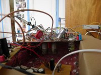
I did use a four-layer board for my sigma-delta audio DAC, though. Any crosstalk from the sigma-delta modulate to the voltage reference or clock increases the noise floor of a sigma-delta DAC. On a point-to-point prototype (see the photograph), just touching the outer insulation of a thin coaxial cable that carried the sigma-delta modulate was enough to increase the noise by 10 dB or so.
I did use a four-layer board for my sigma-delta audio DAC, though. Any crosstalk from the sigma-delta modulate to the voltage reference or clock increases the noise floor of a sigma-delta DAC. On a point-to-point prototype (see the photograph), just touching the outer insulation of a thin coaxial cable that carried the sigma-delta modulate was enough to increase the noise by 10 dB or so.
Attachments
Ooops, apologies that I slipped into audio amp jargon and you had indicated you're a noobie. OPS = output stage.
Full AB actually becomes B. But yes I concur - the degree of 'A'ness determines how messy those currents are. Even in full A (assuming here its PP A where PP=push-pull) there may well be signal-correlated currents in the rails. The only way I've so far found to reduce those to zero (to a first order) is to go SE classA. SE means 'single ended' - using a current source as pull-up and putting the active device in shunt with the load.
Wow, that's class A with a vengeance! Your results suggest a couple of things to me: only your described method of doing class A is completely effective in reducing rail imbalances, and perhaps distortion; PSRR (Power Supply Rejection Ratio) is not as good in most/all amplifiers as some authors have said.
Fascinating! I had no inkling that mutual inductances might be an issue at audio frequencies. Certainly above a few hundred MHz in some applications, but not "down around DC" as an old Tektronix engineer once remarked. I'll have to think about this hard.You might find some of this discussion interesting, about load currents in classAB : -290 dB Distortion?
Just thinking aloud, even *single* layer (plus a few jumpers here and there) work very well in Power Amps.
Hey, power amps can sometimes be built point to point, no board involved!!!!
I'm sure they can. I've built many small test circuits, "dead bug" style.
Such considerations are critical in proper layout of switching power supplies.Just a little worried about important current going through hidden/buried tracks, and through vias connecting them to other planes.
Clever technicians often accomplish miracles.And fully burnt tracks are a fact of life in power amps if accidents happen.
Often repaired with a piece of wire , not sure how could that be accomplished on a buried track.
All such thinking helps me.On the other side, don´t see the real NEED for 4 layers, boards can´t be "too" compact anyway because parts are large and hot.
Again, just thinking aloud.
Two layers are usually more than enough for audio amplifiers. For the reasons abraxalito gave, maybe four layers can come in handy when you strive for extremely low distortion figures.
That's what I hope to with my design (only on paper at present). Perhaps a good experiment would be to build two PCBs, in 2 and 4 layers, and look at the results.
Just as a by-the-way, my goal here is just to play around with ideas I put on hold due to having to earn a living. Now that I'm retired, I have the time, but my ears have gone to pot.

Pretty good! But wouldn't you consider using a copper-clad board kind of a half-way multilayer board?In any case, my class-AB amplifier with 0.006 % distortion at 10 kHz (0.0025 % at half power) is built point-to-point above a piece of copper-clad board.
Not really, I think my amplifier's loop areas are larger than on a two-layer board with one side used as a ground plane, as long as the ground plane side doesn't get interrupted by long signal traces. (That is, if you need to use the side with the ground plane to make a crossing, let the signal go back to the normal side as soon as possible.)
I suppose it depends on your definition of "significantly". I generally find that a 4-layer board made in Canada costs ~50% more than a 2-layer board. Yes, the 4-layer is more expensive, but for a one-off for a hobbyist, it shouldn't hold anyone back.
Outfits like OSH Park will make you three copies of a 4-layer board for $10/sqin. That's really quite good.
Now, about the layout itself: The high-current traces in a power amp are the connections to the output stage. If your plan is to apply a rectified DC voltage to the PCB (rather than having the power supply on the PCB as well) you can just connect it by the output stage. Then you need to run a few low-current traces to the input and driver stage. No biggie. So I generally find that I'm not limited by two layers.
For line level circuits where a split power supply is routed everywhere on the board, I really like using a 4-layer board. Use three layers for the power supply and route the signals on the top layer. This allows me to optimize the signal routing for the best signal integrity without having to worry about having to snake the power supply through at a later stage.
Tom
I find that difference in cost o f 4-layer vs. 2-layer with some custom options like weight of copper on all layers, thickness of pcb, etc. can nearly double even for 10+ boards. I do not order in Canada as I couldn't find anything of better quality than Chinese manufacturers can offer for a comparable price, and also not in OSH Park as they missing features I like to have and also it gets expensive for the larger boards. But as you said it shouldn't hold anyone backI suppose it depends on your definition of "significantly". I generally find that a 4-layer board made in Canada costs ~50% more than a 2-layer board. Yes, the 4-layer is more expensive, but for a one-off for a hobbyist, it shouldn't hold anyone back.
Outfits like OSH Park will make you three copies of a 4-layer board for $10/sqin. That's really quite good.
Now, about the layout itself: The high-current traces in a power amp are the connections to the output stage. If your plan is to apply a rectified DC voltage to the PCB (rather than having the power supply on the PCB as well) you can just connect it by the output stage. Then you need to run a few low-current traces to the input and driver stage. No biggie. So I generally find that I'm not limited by two layers.
For line level circuits where a split power supply is routed everywhere on the board, I really like using a 4-layer board. Use three layers for the power supply and route the signals on the top layer. This allows me to optimize the signal routing for the best signal integrity without having to worry about having to snake the power supply through at a later stage.
Tom
. For a layout preference, i'd like to have it all on one board if it makes sense from layout perspective with respect of size of PS caps. Routing principal same as yours; inner layers power, top signal, bottom common with shortest possible dives to the common layer id it absolutely required. Usually that works well.There's little need for a ground plane at all in an audio power amp - the frequency is too low.
Once you are upto MHz it will matter much more. RF boards use at a minimum a groundplane, and often screened boxes and cans too. This prevents howl-around if there is gain in the circuit, and reduces signal contamination between different sections. Stray capacitances of < 1pF can act as fairly low impedances once up in the 10--100MHz area.
Audio is ~4 orders of magnitude away from this. However if the amp has a very wide bandwidth (unnecessarily wide?) then you may need to treat it more like RF circuitry.
Groundplanes provide a degree of screening from electric field, but in a power amp its the magnetic fields from the large currents that will typically cause issues at the higher audio frequencies, coupling to the more sensitive parts of the circuit - the key point is to keep inductance low for the high current paths by minimizing current loop area.
The inductance itself itsn't very important, the magnetic interference it causes is - if there isn't a stability issue there can often be an inexorable 20dB/decade rise in distortion at HF caused by such coupling if the layout isn't careful to address this. Groundplanes won't do much to prevent this except where they act as a low-inductance return for high currents. Many amps just stuff the output inductor right on top of the circuitry - often this defines the HF performance of the amp as an air-cored inductor can directly inject distortion into the speaker output when its near the rail current paths. Best to have it off the PCB entirely (the Zobel network must be on the pcb though, this is usually essential for stability).
In a star-ground layout correctly applied non of the IR voltages across ground wiring at the high-current end of the pcb are visible to the input side of the circuit. Sloppy layout can get this wrong, and such IR voltages leak signal back to the rest of the circuit at all frequencies, and can push the distortion floor right up if the currents involved were rail-currents (rather than the undistorted speaker current).
A particular point with layout is to ensure the voltage the feedback network (and its ground point) sees is an accurate sample of what the speaker terminals see - the node between the output devices/emitter resistors and the speaker terminal is where highly non-linear currents combine to produce a hopefully linear resultant, you must run the feedback take-off trace from the speaker terminal itself, not the trace between the output devices where significant IR voltages exist, to get the lowest distortion poss.
A groundplane in 1oz copper PCB is however very low resistance (0.5 milliohm-per-square), so if you use a groundplane the IR voltages will be small, you won't have catastrophic problems, you'll just not be able to get down the ppm levels of distortion that good star-grounding can achieve. Its worth noting that the main rail decoupling capacitors in a ground plane pcb will be the points that distorted currents are injected into the ground-plane - keeping these on a separate piece of groundplane will help things a lot. (Assuming you got the feedback take off point correct)
Last edited:
My thoughts, multilayer PCBs with solid ground plane are essential for lower voltage circuits that are high frequency, might have lots of switching current (either from a PSU or DSP etc). Sort of circuits that could radiate lots of noise, or that are susceptible to noise, or that need a solid ground plane so the 0V stays close to 0V and doesn't bounce around. Or that just need the routing space (like BGA parts).
Depends on amp type (Class A/AB vs D) but with A/AB power amps this seems redundant and not needed. EMC should at worse result in some output noise that doesn't really matter too much. If a multi layer PCB is better for current handling, then you could just use thicker copper on 2 layers. The multilayer board might be better for power dissipation.
With Class D likely more complex.
JPS64 said about high voltage routing on multilayers. Last time I looked (up to circa 600V), if I remember correctly, you couldn't guarantee the FR4 layer would be 100% solid so there are limits to this. Still need decent clearance/creepage gaps if you push the voltage up.
I recently built some 4 layer boards at the Chinese fab JLCPCB. They charged me about 33% more than the price of a same size 2 layer board. Interestingly, this was approximately the same price increase as their fee for 2 oz copper: about 33% more than the same board using 1 oz copper.
But I was ordering small boards (60 x 150) in small quantities (30 pieces). I'm sure the percentages change for big orders of large boards.
But I was ordering small boards (60 x 150) in small quantities (30 pieces). I'm sure the percentages change for big orders of large boards.
There's little need for a ground plane at all in an audio power amp - the frequency is too low.
Once you are upto MHz it will matter much more. RF boards use at a minimum a groundplane, and often screened boxes and cans too. This prevents howl-around if there is gain in the circuit, and reduces signal contamination between different sections. Stray capacitances of < 1pF can act as fairly low impedances once up in the 10--100MHz area.
I don't believe high frequencies are necessarily irrelevant for audio amplifiers. An audio amplifier may have a loop bandwidth of a few megahertz, because it needs substantial loop gain at audio frequencies and letting the loop gain roll off at a high slope leads to complications. Besides, it may unintendedly act as a receiver for transmitters that operate at high frequencies. Also the transistors used in the small-signal stages of audio amplifiers usually have an fmax of a few hundred megahertz.
You have a point when it comes to ground planes being far less effective at low than at high frequencies. At high frequencies, the return currents mainly follow the path of least inductance, that is, right below the forward current. At low frequencies, the whole plane is a resistive divider and the return currents spread more than they would at high frequencies. Besides, a copper plane won't shield magnetic fields unless the skin depth is small compared to the copper thickness, that is, the frequency is high enough.
@ohdsp
FR4 = 30kV/mm. You´ve to route high voltage traces in innerlayer. On top and bottom, creepage respecting DIN EN 61010 (VDE 0411). PCB manufactured according multilayer fabrication processes.
Multilayer PCB is defined with manufacturer for cores and prepregs according your specifications (Z0), so yes, multilayers are more expensive then standard FR4 1.6.
JP
- Home
- Design & Build
- Construction Tips
- Two layer versus four layer PCBs