This Project is finished succseeful
Hi Guys
Ok today is Saturday October 17th, its 5:50 PM, the Class A Single End amplifier has been build finish this morning 940am.
I have made some sound files and will place them on Utube, but I'm not really satisfied with the files, because the Record which I actually started, made unessecary noise, but I had to be in office at 11:00am. so time wasn't enough. Tomorrow I will record some sound Sequences again, just that you become an Idea how the sound is,.
Turntable will be REVOX B795, CD Player will be Philips 850 One bit
Line drive Preamp will be Audio Research SP9
Speakers I.Q. Series 4
No Tone Control or Subwoofers will be involved. It is of advantage if you listen to that files with headphone, as the files are recordet, with a Nikon P7800 HD in Stereo.
I will share some classic musis, some Rock Music, and some Orchestral Music.
Each file will be about 15 - 20 or more Minutes.
I know this is not the sound as listen to the amplifier, but it gives you an idea what is to expect when hearing this amp in real time..
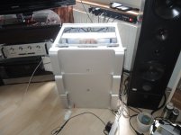
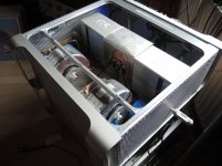
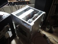
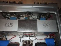
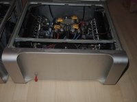
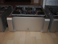
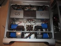
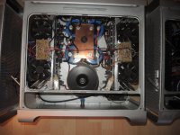
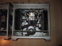
Feets have been glued to the botton plate, and you see in picture 1 that this is the third amplifier in this line, with this case., the case is an old G5 Macintosh Computer Case.
The Active Heatsinks are also from this case.
The Amp in this configuration as it is set now, with 21 Watts @ 8 Ohm will heat to about 65Degrees Celcious, and the Back Heatsinks with Emitter Resistors will heat up to 85Degrees..
If it is switched to 28 Watts, then heat of the amp will increase to max 72 degrees and the back heatsinks will be at 98Degrees Celcious.
The Fans speed is set at 1000RMP, so it generates only very little noise, almost not hearable in a real quiet Room. it is about 14 db.
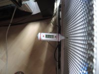
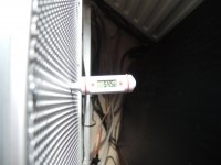
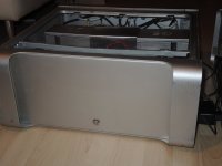
The sidepanels are increasing the heat inside the Active Sinks because of the meshhole which are only 2.5 mm in size. I will enlarge them later when there is need of.
Not having the panels on heat goes down by about 5 - 7 degrees per side.
Both sides have been run last night for about 4 hours already and max heat I could measure with closed Top, was 65Degrees Celcious, for me absolutely passable.
So project has finished, but I also have Class A Singel End Line drive in my thought, with a Tube pre amp for the Turntable..
I like to express my respect to all of you here and like to thank everyone, and everybody that i could be a part of the tremedous sohisticated Site here.
Special thanks go to Nelson Pass, because he was that person, who asked me to come here, even I registered 2012, but I never posted anything of my work.. Because out there are many more who do a much better job than I do,
This amp just has to be a little project for this site here.
Thank you all
Regards and with respect
Chris Hess
Hi Guys
Ok today is Saturday October 17th, its 5:50 PM, the Class A Single End amplifier has been build finish this morning 940am.
I have made some sound files and will place them on Utube, but I'm not really satisfied with the files, because the Record which I actually started, made unessecary noise, but I had to be in office at 11:00am. so time wasn't enough. Tomorrow I will record some sound Sequences again, just that you become an Idea how the sound is,.
Turntable will be REVOX B795, CD Player will be Philips 850 One bit
Line drive Preamp will be Audio Research SP9
Speakers I.Q. Series 4
No Tone Control or Subwoofers will be involved. It is of advantage if you listen to that files with headphone, as the files are recordet, with a Nikon P7800 HD in Stereo.
I will share some classic musis, some Rock Music, and some Orchestral Music.
Each file will be about 15 - 20 or more Minutes.
I know this is not the sound as listen to the amplifier, but it gives you an idea what is to expect when hearing this amp in real time..
Feets have been glued to the botton plate, and you see in picture 1 that this is the third amplifier in this line, with this case., the case is an old G5 Macintosh Computer Case.
The Active Heatsinks are also from this case.
The Amp in this configuration as it is set now, with 21 Watts @ 8 Ohm will heat to about 65Degrees Celcious, and the Back Heatsinks with Emitter Resistors will heat up to 85Degrees..
If it is switched to 28 Watts, then heat of the amp will increase to max 72 degrees and the back heatsinks will be at 98Degrees Celcious.
The Fans speed is set at 1000RMP, so it generates only very little noise, almost not hearable in a real quiet Room. it is about 14 db.
The sidepanels are increasing the heat inside the Active Sinks because of the meshhole which are only 2.5 mm in size. I will enlarge them later when there is need of.
Not having the panels on heat goes down by about 5 - 7 degrees per side.
Both sides have been run last night for about 4 hours already and max heat I could measure with closed Top, was 65Degrees Celcious, for me absolutely passable.
So project has finished, but I also have Class A Singel End Line drive in my thought, with a Tube pre amp for the Turntable..
I like to express my respect to all of you here and like to thank everyone, and everybody that i could be a part of the tremedous sohisticated Site here.
Special thanks go to Nelson Pass, because he was that person, who asked me to come here, even I registered 2012, but I never posted anything of my work.. Because out there are many more who do a much better job than I do,
This amp just has to be a little project for this site here.
Thank you all
Regards and with respect
Chris Hess
Attachments
-
 1. Class A Linear Single End.jpg148.8 KB · Views: 241
 -
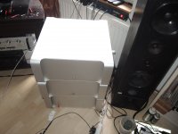 9. Class A Linear Single End closed.jpg131.6 KB · Views: 76
 -
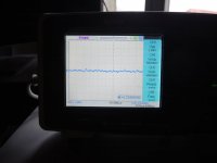 8. Class A Linear Single End - Scope Audio Measure.jpg90.8 KB · Views: 86
 -
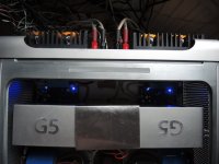 7. Class A Linear Single End - the Amplifiers.jpg159.7 KB · Views: 91
 -
 6. Class A Linear Single End - Fan Regulation.jpg151 KB · Views: 94
 -
 5. Class A linear Single End - Temp Left Side.jpg141.9 KB · Views: 224
 -
 4. Class A linear Single End - Temp right Side.jpg114.1 KB · Views: 227
 -
 3. Class A linear Single End - Right Side.jpg207.7 KB · Views: 230
 -
 2. Class A linear Single End - Left Side.jpg177.1 KB · Views: 233
A few Amps build in the last 7 Years
Guys,
Here I like to share a few pictures from amplifiers I build in the past 7 - 10 years,
I can not show all here because of, some are in my second home in Thailand, and the other ones I need to pull out of the compartments which they are in,. then a few aren't even in a BOX, just mounted on heat-sinks.
Here the MAC Series, the name because the Box is an G5 APPLE case.
The first is a amplifier I first build in Thailand 30 Years ago, but never took that amp to Swiss. I used the circuit I have placed here, is an Common Collector Load, Emitter follower, where we have 5 Current Source Transistors, and then 5 Signal transistors. Controlled with a PID Circuit. Runs at +- 48 Volts, has a Loudspeaker Protection circuit as as well a *NOT WORKING* fan Control on the amplifier board.. Power output RMS is 20 Volts = 50 Watts from 10 HZ - 100khz
sounds good and till now it is never broken down. Max Heat is 80Degrees Celsius, with a Cut off main Power at 100Degrees Celsius. has 10 Output transistors, MJL4281, it takes four 6inch Fans running at 600 RPM to have it cool at 80degrees. Before this one was born there were at least 6 Different Test amps all in working condition.
The second one is also Class A, but this is a full modification of Rod Elliot Death of Zen Amp.
His amp runs only on + Rail and GND. I think it was 24 volts.
So in fact there is not much except the Input stage of Rod Elliot Amp which can be recognized as a Circuit of Rod. Gain Adjustment and Current Source adjustment, which i needed to modify as well because the amp was running away when temp changed, therefore I also added a PID control which eliminated the use of a Current Source Control. But it is still on the board, but as soon PID kicks in, the that VR is cut out.
I made a new output stage and a new Driver stage, they are similar to Rod Elliot Original zen of Death, but mine don't use Bootstrap Caps, no feedback Caps, dual Rail voltage of +- 48 volts also as again 10 MJL4281 Output Transistors. I did send a EMAIL to Rod with the modified Version, so he knows what I was doing, BTW he also answered me.,.
Power output and Frequency band is same as the one above.
Sound is more clear and sweet, has no protection circuit on board. Except the input RAIL FUSES and RAIL Diodes, so applying the power Rail the wrong way will do nothing,..Here also I made 6 test Versions until I got the one you can see in the picture.. Transformers are 2x35-035 Volts with 7.5 Ampere
Double Bridged per Side, 68'000uf per + and 68'000uf per - Rail
Amp can be run at an Idle of 10 Ampere without have to worry that it blows up. Because I like to close the box while listening to the amp this one works at 2.8Ampere idle.
The last on you know the data already, but big difference is. it is SINGLE END, it uses only two POWER OUTPUT TRANSISTORS, max OP is 28 Watt by an IDLE of 5 AMPERE. The this one uses Active Cooling, noiseless.,
sound is extreme better the other two.. This I made 20PCB till I got this one which is build in, I started out with just an IC and one Power Transistor, MJL4281, and when the circuit was there, I send Mr. Nelson Pass to verify, and he responded to remove that IC, what I did, But again, I'm some kind of lazy when it comes to make complicated Circuits, and when I had a two transistor version ready I was again in need to have DC at the output running away, not much but to much for me, so I decided, instead of calculating the amp again and again, to use that PID which never failed, and that's why I have at the output without signal, open input or short don't matter a max of .01Millivolt and under full use or full load it will change to max not more than 60 Milli-volts.. for me totally Acceptable. I do not build amps to sell, I just have fun with building it..
I made these Sound files again today, but my film and sound equipment is not good enough, So I need to get better equipment, so I can let you have a sound test of all this tree amp.
Give me a few Days, then it will happen.
Here again a few Pictures of these amps.
Thanks you for reading, you guys are great and welcome.
Regards
Chris
Attachments
-
 9. Class A Single End Amplifier Build 2020 - PCB View.jpg198.4 KB · Views: 68
 -
 8. Class A Amp Build 2017 - PCB View.jpg420.2 KB · Views: 77
 -
 7. Class A Amp Build 2013 - PCB View.jpg377.8 KB · Views: 70
 -
 6. Class A Amp Build 2013 - Front view.jpg144.2 KB · Views: 64
 -
 5. Class A Power Amp Buil 2017 - Front View.jpg140.6 KB · Views: 58
 -
 4. Class A Single End Build 2020 - Front View.jpg115.9 KB · Views: 81
 -
 3. Class A Single End, Build 2020 - Top View.jpg199.4 KB · Views: 89
 -
 2. Class A Power Amp Build 2017 - Top view.jpg245.3 KB · Views: 94
 -
 1. Class A Build 2013 - Top View.jpg195.3 KB · Views: 93
 -
 Class A Amps Hpro.jpg160.3 KB · Views: 62
Last edited:
To be Continued.
Guys
We have December 10th 2020 here in Switzerland, snow is falling, cold it's also.
Corona gets around everywhere and shows it's destruction, leaving a Valley of deaths.
But this is not what is on my mind.
After the The Single End Class A Amp has been Build and now it has runs already over 500hours of time, just switched on, or on low level output on 3.8 Ohm speakers, it heats up to 62 resectively 66 degrees, so one channel is slightly hotter than the other one.
The amp runs without any SPEAKER PROTECTION CIRCUIT. everyday at least for 8 hours. With this I mean when I return from office at 4pm to midnight. there are so far no hickups, or repairs, distortion or likewise.
Since I build that Amp, with these two paralelled MJL4281 Transistors at the output which makes that Single end, I designed, an other version with 6 Transistors. Pararlell. The same cirquit with slight changes, and also increased IDLE current to 5 Amps. instead of 3.8Amps @42Volts.This means new Transformers, and I'm ready to take it to the limit with +- 50 Volts.
This makes it necessary that the cooling speed of these 4 Noctua Fans have to be increased by a 100rpm, but only that much that there no noise increase can be heard.
I already drew and etched a new double sided test PCB and this time, the outcome is like a dream. I'm redesigning it at present time, to a smaller Size as I have it right now, so it can be just excheanged with the one wich is inside.
I promised to place Circuits and specs as well as Outlines here, and this is still what I'm going to do. Only I want to be sure that who ever might invest money to build, can build it easy and without hickups. So, as soon the amp reached 750 hours running time without the need to be repaired, I will place all the what I promised here on this Site.,
The new version of the Amp should be ready in a week or two, it already has been tested and the only reason I'm desinging it, I want to be able to go down to 2 ohms for the load.
So that's it for today.
Regards
Chris Hess
New PCB made
Guys
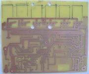
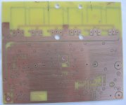
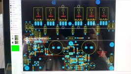
So in the meantime, I have finished the new drawn, tested and designed PCB for the Amplifier. Fitting exact to the layout of the at present time build in amplifiers. Actually there is no need to changes anything, but because of another Lock-down here in Swiss, because of Corona Virus, I have too much Spare time, so, I must do something, not to waste the Time unused. there is not much left on it, and that's why I again took out my designing tools, and made a 6 Transistor Version of that last build. just for fun.
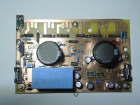
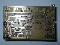
So here are the results of the PCB and also the Drawings.
The newly made PCB have just been cleaned, not polished yet. this will be done just before assembling it tomorrow, at least I hope so. the only difference to the one I use right now is
6 Transistors at the output in parallel
For input Transistor I made a Plug and Play version, if there is a need to exchange, no soldering is needed.
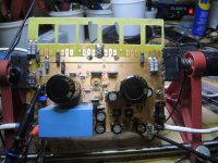
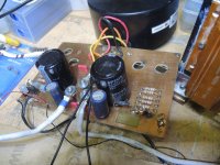
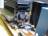
Also for Input Transistor Collector Pin, I added a ripple filter that the transistor pulls less hum from power-supply, with two 12000uf/50volts capacitors, as RC element R= 560Ohm - C=12000uf which can be changed to get better or less hum on the collector pin. This transistor is operating at it's limits so it was necessary to add this filter. also for the Plus Line of it there is the same filter one more time. you can see in picture 1 these two big Caps.
Bandwidth is supposed to be 10hz - 200Khz +- 0.2 DB from over the full output range.
Input impedance is 22KOhm
Max Output at 4 Ohms is 35Watts,
8 Ohm should be 28.7 with idle at 7.4 ampere at +-38 Volts Rails.
Over all gain is 7.
Heat should not exceed 75Degrees Celsius. Using 2 Fans to cool it down, running low speed at 600rpm and a noise level of max 10db.
I can't talk about signal / noise Level of the amplifier itself, in reality, but this will be revealed as soon the amp has been assembled and power applied.
Here also have a Pictures for you.
Thanks for reading, hope that this will be finished, meaning that I can listen to it within the next couples of days.
To be continued
Regards Chris Hess
Guys
So in the meantime, I have finished the new drawn, tested and designed PCB for the Amplifier. Fitting exact to the layout of the at present time build in amplifiers. Actually there is no need to changes anything, but because of another Lock-down here in Swiss, because of Corona Virus, I have too much Spare time, so, I must do something, not to waste the Time unused. there is not much left on it, and that's why I again took out my designing tools, and made a 6 Transistor Version of that last build. just for fun.
So here are the results of the PCB and also the Drawings.
The newly made PCB have just been cleaned, not polished yet. this will be done just before assembling it tomorrow, at least I hope so. the only difference to the one I use right now is
6 Transistors at the output in parallel
For input Transistor I made a Plug and Play version, if there is a need to exchange, no soldering is needed.
Also for Input Transistor Collector Pin, I added a ripple filter that the transistor pulls less hum from power-supply, with two 12000uf/50volts capacitors, as RC element R= 560Ohm - C=12000uf which can be changed to get better or less hum on the collector pin. This transistor is operating at it's limits so it was necessary to add this filter. also for the Plus Line of it there is the same filter one more time. you can see in picture 1 these two big Caps.
Bandwidth is supposed to be 10hz - 200Khz +- 0.2 DB from over the full output range.
Input impedance is 22KOhm
Max Output at 4 Ohms is 35Watts,
8 Ohm should be 28.7 with idle at 7.4 ampere at +-38 Volts Rails.
Over all gain is 7.
Heat should not exceed 75Degrees Celsius. Using 2 Fans to cool it down, running low speed at 600rpm and a noise level of max 10db.
I can't talk about signal / noise Level of the amplifier itself, in reality, but this will be revealed as soon the amp has been assembled and power applied.
Here also have a Pictures for you.
Thanks for reading, hope that this will be finished, meaning that I can listen to it within the next couples of days.
To be continued
Regards Chris Hess
Attachments
-
 5. Class A Bottom Side with heatsink Mounted Version 9.5.jpg148.7 KB · Views: 57
 -
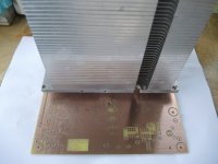 4. TOP Side PCB woth Heatsink mounted - Version 9.5 - Testing.jpg140.4 KB · Views: 58
 -
 3. Class A Bottom Side Version 9.5.jpg150.4 KB · Views: 72
 -
 2. Class A TOP Side Version 9.5.jpg168.2 KB · Views: 84
 -
 1. layout Class A version 9.5.jpg218.6 KB · Views: 90
Last edited:
Assembling the board
Guys,
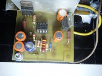
Started to assemble this morning at 9am.. it's still about 5 hours to hear the sound of it, as I take it easy and there will be 2 hours Noise & HUM testing in a few minutes, this without transistors or any load on the board, just the Regulation part as well as SERVO part. Servo or PID is the 2 IC's on the right side of the board, left side *IC SOCKET* is for input Signal Transistor, and driving stage only. PID does correct only DC Levels at the output without interfering with the Signal of the Amplifier. So, it just makes sure that always 0Volt DC is at the output, despite the input voltage. It will fluctuate a little bit, which is approximately 10 millivolts maximum, at any output level, as long the amp is in it's working point and doesn't clip. Up to 1% clip on the output there is no danger of DC to appear at the output. PID will take care just fine.
Now it's a few minutes past 11 am here Swiss, in the afternoon we will be able to listen to it.
BTW this board will fit any heat-sink not only active ones.
As for now, Happy Sunday
Cheers
Regards
Chris Hess
Here a Picture, of the board almost assembled in full and ready to test for Hum and other eventually appearing not designed and not wanted outcomes.
Guys,
Started to assemble this morning at 9am.. it's still about 5 hours to hear the sound of it, as I take it easy and there will be 2 hours Noise & HUM testing in a few minutes, this without transistors or any load on the board, just the Regulation part as well as SERVO part. Servo or PID is the 2 IC's on the right side of the board, left side *IC SOCKET* is for input Signal Transistor, and driving stage only. PID does correct only DC Levels at the output without interfering with the Signal of the Amplifier. So, it just makes sure that always 0Volt DC is at the output, despite the input voltage. It will fluctuate a little bit, which is approximately 10 millivolts maximum, at any output level, as long the amp is in it's working point and doesn't clip. Up to 1% clip on the output there is no danger of DC to appear at the output. PID will take care just fine.
Now it's a few minutes past 11 am here Swiss, in the afternoon we will be able to listen to it.
BTW this board will fit any heat-sink not only active ones.
As for now, Happy Sunday
Cheers
Regards
Chris Hess
Here a Picture, of the board almost assembled in full and ready to test for Hum and other eventually appearing not designed and not wanted outcomes.
Attachments
Postponement to a later day, Chrismas I think it will be finish
Guys
Actually I thought the Amp would be finished, but it is not.
Reason some very basic circuit on the board will not function as I thought it would.. And I could laugh, I could cry, I could swear to god, or getting angry at myself, but it doesn't help, it just don't work.
No the Amp itself at least the Input I could test, and this works just beautiful. Better than I thought. But Regulation of the PID Section don't work. With this I mean, the 7818 and 7918 refuse to output the correct voltage, and in the end both of them stop to work. Now I think, it's because I did not connect the Power Transistors and the drive, so the Overall Input Voltage on the +- 18 volt rail Regulators, for the IC's gone to high, * limit is 35Volts* and this may destroyed them. Never happen before. So, it makes no sense, that I'm working on it longer as I already did, because I do not have Spare Regulators at home, and I could not go and buy any, at least not today. Tomorrow I will be able to order to buy them.
But what I tested is hum and noise for the input and it's very low around 3mv @48Volts Rail voltages, always talking about +-. So actual Rail between + and - is 96volts.
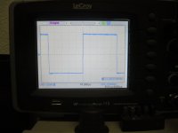
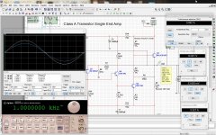
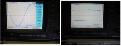
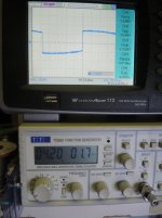
Sine Wave will start to clip at 15.6Volts, so this what you see is just a part of the output voltage, it can make.
And if I get these 15.6 volts into 4 Ohms or better into 2 Ohms, then I think that amp is just as good or better than these Push-pull Class A. the ones just working with 2amps or likewise, this here is sucking as much as 7.4 Amps IDLE.
When I was young there was a saying, a CLASS A which don't get Hot is not CLASS A.!
Oh, I saw the Grand Master went back to create a OTL Class A. First Watt F8!
So, something must be there that even the Grand Master of Amplifiers is going back to Single End Amplifiers. And he is using Single RAIL Voltage as well, and I'm sure it just sounds great, wouldn't expect anything else for the Grand Master himself. He inspires me, with that kind of thoughts.
It's just difference, to anything else, not talking about these Bulb Amps, has nothing to do with them!
Talking about Transistors, only.And not Mosfets as well.
So I will need to replace these regulators, and then I think I'm a big step into the right direction.
Also need to use another Transformer as long the Power Transistors haven been connected, as the output voltage of the Toroid is far to high,. +- 48 Volts, then a drop resistor for the Regulators, usually works like a champ. It did not work today.. Taking the voltage down to +- 38 and it will work.Then go over it again and start do calculate it one more time.
Why ever or because what's the reason for I do not know yet, and I'm also are not going to find out today, making TV evening, or listening to some good Vinyl Records, but Stop right now to work on that Board.
So, guys for all who are not in Europe, enjoy Weekend, I think your day just started, all in the East, sleep well and for the rest here have a nice evening.
Regards.
Chris Hess
Guys
Actually I thought the Amp would be finished, but it is not.
Reason some very basic circuit on the board will not function as I thought it would.. And I could laugh, I could cry, I could swear to god, or getting angry at myself, but it doesn't help, it just don't work.
No the Amp itself at least the Input I could test, and this works just beautiful. Better than I thought. But Regulation of the PID Section don't work. With this I mean, the 7818 and 7918 refuse to output the correct voltage, and in the end both of them stop to work. Now I think, it's because I did not connect the Power Transistors and the drive, so the Overall Input Voltage on the +- 18 volt rail Regulators, for the IC's gone to high, * limit is 35Volts* and this may destroyed them. Never happen before. So, it makes no sense, that I'm working on it longer as I already did, because I do not have Spare Regulators at home, and I could not go and buy any, at least not today. Tomorrow I will be able to order to buy them.
But what I tested is hum and noise for the input and it's very low around 3mv @48Volts Rail voltages, always talking about +-. So actual Rail between + and - is 96volts.
Sine Wave will start to clip at 15.6Volts, so this what you see is just a part of the output voltage, it can make.
And if I get these 15.6 volts into 4 Ohms or better into 2 Ohms, then I think that amp is just as good or better than these Push-pull Class A. the ones just working with 2amps or likewise, this here is sucking as much as 7.4 Amps IDLE.
When I was young there was a saying, a CLASS A which don't get Hot is not CLASS A.!
Oh, I saw the Grand Master went back to create a OTL Class A. First Watt F8!
So, something must be there that even the Grand Master of Amplifiers is going back to Single End Amplifiers. And he is using Single RAIL Voltage as well, and I'm sure it just sounds great, wouldn't expect anything else for the Grand Master himself. He inspires me, with that kind of thoughts.
It's just difference, to anything else, not talking about these Bulb Amps, has nothing to do with them!
Talking about Transistors, only.And not Mosfets as well.
So I will need to replace these regulators, and then I think I'm a big step into the right direction.
Also need to use another Transformer as long the Power Transistors haven been connected, as the output voltage of the Toroid is far to high,. +- 48 Volts, then a drop resistor for the Regulators, usually works like a champ. It did not work today.. Taking the voltage down to +- 38 and it will work.Then go over it again and start do calculate it one more time.
Why ever or because what's the reason for I do not know yet, and I'm also are not going to find out today, making TV evening, or listening to some good Vinyl Records, but Stop right now to work on that Board.
So, guys for all who are not in Europe, enjoy Weekend, I think your day just started, all in the East, sleep well and for the rest here have a nice evening.
Regards.
Chris Hess
Attachments
Last edited:
Finalized Prototype 2 - on Christmas Day
Everybody have a MERRY MERRY CHRISTMAS
As promised I'm back at Christmas day, with a Working Prototype 2 of Version 9,5 of my Class A Amplifier Designs.
In the post prior to this I mentioned the Regulator Problem, which I could locate the problem after a very intensive Search. And again it's just nothing more but true, that if we produce PCB which looking like a Dream, and this one it does exactly this, Control, will be less or none or just fast, too fast so error Occur.
Here it was the DOUBLE SIDED PCB Phenomena, at least I call this like that.
On the top side, one Donuts of the Regulators "Output and Protection Resistor" had a very thin copper-lead to Ground Plane, as especially at this Donuts distance to Ground-plane is only .1mm.
So today I build in the rest of it, and all turned out better that I expected.
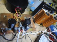
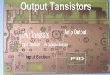
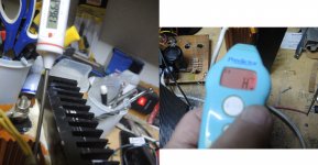
Have made some Pictures of the Board, the Power Consumption, then also from Input Transistor which I placed into a Socket, and also from Drive.
At present Time, the Amp is working with 2 Output Devices only, because of this board is as I wrote above Prototype 2, the board which I'm going to use should be finish, on Sunday, as well two layers but this time without any Short connections.
The Sound is extremely Natural, listen from Record Player over my Mixing Console, just to have it amplified the Needle.. MM just for the case.
A full Spec I will make tomorrow, with all what it takes, and then I hope Monday or Tuesday the new components for Final Version 9.5.10 will arrive from USA, Mouser.
So at the end of the year, I should be able to replace that Amp with the one I have in the box.
Cheers everyone,
Enjoy Christmas. I also do, working.
Regards
Chris Hess
Everybody have a MERRY MERRY CHRISTMAS
As promised I'm back at Christmas day, with a Working Prototype 2 of Version 9,5 of my Class A Amplifier Designs.
In the post prior to this I mentioned the Regulator Problem, which I could locate the problem after a very intensive Search. And again it's just nothing more but true, that if we produce PCB which looking like a Dream, and this one it does exactly this, Control, will be less or none or just fast, too fast so error Occur.
Here it was the DOUBLE SIDED PCB Phenomena, at least I call this like that.
On the top side, one Donuts of the Regulators "Output and Protection Resistor" had a very thin copper-lead to Ground Plane, as especially at this Donuts distance to Ground-plane is only .1mm.
So today I build in the rest of it, and all turned out better that I expected.
Have made some Pictures of the Board, the Power Consumption, then also from Input Transistor which I placed into a Socket, and also from Drive.
At present Time, the Amp is working with 2 Output Devices only, because of this board is as I wrote above Prototype 2, the board which I'm going to use should be finish, on Sunday, as well two layers but this time without any Short connections.
The Sound is extremely Natural, listen from Record Player over my Mixing Console, just to have it amplified the Needle.. MM just for the case.
A full Spec I will make tomorrow, with all what it takes, and then I hope Monday or Tuesday the new components for Final Version 9.5.10 will arrive from USA, Mouser.
So at the end of the year, I should be able to replace that Amp with the one I have in the box.
Cheers everyone,
Enjoy Christmas. I also do, working.
Regards
Chris Hess
Attachments
-
 7. Emittor Resistor Paralell 7.5 Ohms 400 Watts.jpg204.9 KB · Views: 51
 -
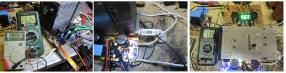
 6.Class A Version 9.5 Power Consumptiom.jpg226 KB · Views: 46
 -
 5. Powersupply +-40 Volts 7.5 Ampere.jpg230.8 KB · Views: 48
 -
 4. Power Supply & Emiiter Restistor of Output Transistors.jpg222.6 KB · Views: 42
 -
 3. Input & drive Transistors dual Stage.jpg153.6 KB · Views: 54
 -
 2. Input Transistor BC556 mounted in Socket.jpg140.1 KB · Views: 54
 -
 1. Class A Single End Amplifier - Paralell 6 MJL4281 Outputs - Working.jpg239.5 KB · Views: 54
Another day, another time, alsmost done.
Guys
So still Christmas here in swiss, 26th of December 2020, made 2 *I hope final * double Layers PCBs, today, not etched yet, but this will happen tomorrow.
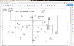
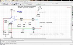
For anyone who is interested into this Amp I also add the Circuit of the amp.
Making the PCB use WIDE LINES for C and E 5mm is minimum
The Base Resistor of the Output Transistor, I use 4X 3 Watts of 820 Ohms to get that 205 Ohm which makes that Transistor to work.
Idle Current is the Value of V- *NEGATIVE RAIL VOLTAGE* devided by RE of MJL4281, this also counts for Max Power Output of the amp.
This is the Basic Circuit, as I use it, Tomorrow I will also place the PID CONTROL of the Amplifier, even without PID the AMP works, very satifiying. This circuit consist only of a few parts but make sure that you select good Parts, as otherwise it will turn out into lots of work and sleepless nights. Make sure that you have adequate cooling and at least a 10 Amp RMS / Per Side Power Supply. The Power Supply can go down to as low as +-24Volts, still 10 Amps, as smaller the Value of RE the more heat and more output power you get. Take a 12 % - 15% Output Voltage for granted according to the Supply or Rail voltage. Using +- 24 Volts RE can be as Low as 4 Ohms so then you would need a RE in Size of 24:4 X 24= Watts 144 Watts for RE. and large (and when I write large then I mean extremly LARGE or ACTIVE COOLING is the other way to go), heatsinks for the Transistors. But you can also go up as high as +-48 volts, Make sure that your PSU can deliver 15AMPS RMS, again this depends on RE.
If you use more than one Output transistor so you need to use for each Transistor also a .1 Ohm 1 Watt resistor which is in Serie with PSU of the RE and Output of the Amplifier, and paralell to the other Transistors, this to make sure that because of none matching HFE, all transistor will heat equally. Matching the Transistor, meaning checking HFE, still needs the Resistors. I spent hours and hours to find a way around it, didn't find one. If you check HFE then make sure that HFE is measured for all Transistor exactly the SAME, meaning say if you have in mind to use HFE =120, then all must be 120. For the drive Transistors I figured out that a HFE of 155 * BD 139-10 or 16* give the best response, as for the BC 556 or BC559, 350 is ok, below that the amp gets Slow in response, to much above you will kill the transistor more easy and output of the amplifier is hard to control.
The PID is straight forward. In fact is just one OP amp which works as voltage *DC* comparator and adjusting the BIAS VOLTAGE of Q1 BC556 or BC559 within only a few millivolts, so the output stay within secured levels, usually without PID +- 200mv with PID about 0= +- 10 mv.
The second IC Socket you see on the board is just to Adjust the first IC to 0.000 Output, even most IC's are adjusted on chip but this function is still there, and it's helpfull when we try to elimiante millivolts. meaning everything below 10 mv.
The circuit also consist of two 12000uf Elko Caps , the can be well less around 1000uf will do as well, but this again depends on Rail Voltage. Those are a low Pass filter, adjusted to .1Hz. The resistor before the ELKO is 15 Ohm wire wound 1%
These are to clean the Rail Voltages for the first and second Transistor. Removing this one, the amp still works but eventually generates hum, which of course can be eliminated with other means.
If supply Voltage isn't higher than +- 60 volts then BC559 is adequate everythings above this its recommendet to use BC556 . Depends on the gain wanted of this amplifier there is might some Noise Cancel around 30 - 60 pf requested, this depends on so many things,
This small cap goes between BC of BC 556 or 559, it will kill all Resonance Oscilation of that Transistor, which can go as high as full level power output in the range of 1 - 5 Mhz.
Gain is controlled by R7&R8 = 510:41 = 12.4 Reducing R7 to 400 Ohms gives more Bandwitdh. Keep R8 as it is.
There is no need of other caps for that amplier, you can use Ceramic or Silvermica * Silvermica is more expensive * I prefer Silvermica, but these are not that easy to come by.
As you can see I do not use any Protection Circuit, but it is requested to USE one, here we are dealing with an AMPLIFIER which is running 288 Watts Constantly neverthless the signal input. Therefore the Transistor generates heat for the half of this 288 Watts, which is 144 and the other 144 are burned in RE. And RE gets Hot, promise. Above 100 Degrees Celcius. The one I'm using now is cooled with Active Cooling and reaches * depends on Room temp* but usally it goes not higher than 69Degrees, and this is already only possible because of 4 Low Noise Noctua Fans. Each one has its own control.
Amp has almost 750 Hours Running time behind it, withou any flaw, and the sound is CLASS A. You get everything what you expect. This Amp runs Stable, without to have to fear that it blows when turning it up.! Why, because it's always on full load already, there is no increase of Amperes or Voltages or changing characteristics because of heat. Just forget about. Here we are talking about Full Power all times, at your hand or the Volume Control. All you add when opening the Trottle is SIGNAL, nothing else, will increase or decrease. CLASS A at it's best. You want to play CLASS A, you need to accept the Downers of it. HEAT, LEAST INPUT OUTPUT RATIO when it comes to POWER USAGE and VERY low Efficiency.
But what you get, there is no other AMP to compare CLASS A. Not Biased Class A, Talking about REAL CLASS A, Single END. ONE Transistor does it all. Just one Question: Why Would a MAN like Nelson Pass Designing a CLASS A OTL = OUT PUT CONDENSER LESS, Single END, Because it's hasn't been beaten at any time. If you don't believe it then Check out the specs of First Watt F8.!
Recently I bought a Gibson Accoustic Guitar for over 1200 USD, and yes I can play, but I bougth it to record, and then to make compare Testing with the sound of the amp the speaker and all what comes with it. Just to hear the Strings Swing, and the Timbre, of it.
Got for many years a Les Paul Studio, but it's electric, so sound is harder to compare than with an Accoustic one.
Got already to long again!
If you find any misspelled words, then I'm sorry, Auto Correct didn't kick in. And English is not my native language.
This shall not be an excuse.
Any Question just ask
Happy Holidays
Regards
Chris Hess,
December 26th. 2020
Guys
So still Christmas here in swiss, 26th of December 2020, made 2 *I hope final * double Layers PCBs, today, not etched yet, but this will happen tomorrow.
For anyone who is interested into this Amp I also add the Circuit of the amp.
Making the PCB use WIDE LINES for C and E 5mm is minimum
The Base Resistor of the Output Transistor, I use 4X 3 Watts of 820 Ohms to get that 205 Ohm which makes that Transistor to work.
Idle Current is the Value of V- *NEGATIVE RAIL VOLTAGE* devided by RE of MJL4281, this also counts for Max Power Output of the amp.
This is the Basic Circuit, as I use it, Tomorrow I will also place the PID CONTROL of the Amplifier, even without PID the AMP works, very satifiying. This circuit consist only of a few parts but make sure that you select good Parts, as otherwise it will turn out into lots of work and sleepless nights. Make sure that you have adequate cooling and at least a 10 Amp RMS / Per Side Power Supply. The Power Supply can go down to as low as +-24Volts, still 10 Amps, as smaller the Value of RE the more heat and more output power you get. Take a 12 % - 15% Output Voltage for granted according to the Supply or Rail voltage. Using +- 24 Volts RE can be as Low as 4 Ohms so then you would need a RE in Size of 24:4 X 24= Watts 144 Watts for RE. and large (and when I write large then I mean extremly LARGE or ACTIVE COOLING is the other way to go), heatsinks for the Transistors. But you can also go up as high as +-48 volts, Make sure that your PSU can deliver 15AMPS RMS, again this depends on RE.
If you use more than one Output transistor so you need to use for each Transistor also a .1 Ohm 1 Watt resistor which is in Serie with PSU of the RE and Output of the Amplifier, and paralell to the other Transistors, this to make sure that because of none matching HFE, all transistor will heat equally. Matching the Transistor, meaning checking HFE, still needs the Resistors. I spent hours and hours to find a way around it, didn't find one. If you check HFE then make sure that HFE is measured for all Transistor exactly the SAME, meaning say if you have in mind to use HFE =120, then all must be 120. For the drive Transistors I figured out that a HFE of 155 * BD 139-10 or 16* give the best response, as for the BC 556 or BC559, 350 is ok, below that the amp gets Slow in response, to much above you will kill the transistor more easy and output of the amplifier is hard to control.
The PID is straight forward. In fact is just one OP amp which works as voltage *DC* comparator and adjusting the BIAS VOLTAGE of Q1 BC556 or BC559 within only a few millivolts, so the output stay within secured levels, usually without PID +- 200mv with PID about 0= +- 10 mv.
The second IC Socket you see on the board is just to Adjust the first IC to 0.000 Output, even most IC's are adjusted on chip but this function is still there, and it's helpfull when we try to elimiante millivolts. meaning everything below 10 mv.
The circuit also consist of two 12000uf Elko Caps , the can be well less around 1000uf will do as well, but this again depends on Rail Voltage. Those are a low Pass filter, adjusted to .1Hz. The resistor before the ELKO is 15 Ohm wire wound 1%
These are to clean the Rail Voltages for the first and second Transistor. Removing this one, the amp still works but eventually generates hum, which of course can be eliminated with other means.
If supply Voltage isn't higher than +- 60 volts then BC559 is adequate everythings above this its recommendet to use BC556 . Depends on the gain wanted of this amplifier there is might some Noise Cancel around 30 - 60 pf requested, this depends on so many things,
This small cap goes between BC of BC 556 or 559, it will kill all Resonance Oscilation of that Transistor, which can go as high as full level power output in the range of 1 - 5 Mhz.
Gain is controlled by R7&R8 = 510:41 = 12.4 Reducing R7 to 400 Ohms gives more Bandwitdh. Keep R8 as it is.
There is no need of other caps for that amplier, you can use Ceramic or Silvermica * Silvermica is more expensive * I prefer Silvermica, but these are not that easy to come by.
As you can see I do not use any Protection Circuit, but it is requested to USE one, here we are dealing with an AMPLIFIER which is running 288 Watts Constantly neverthless the signal input. Therefore the Transistor generates heat for the half of this 288 Watts, which is 144 and the other 144 are burned in RE. And RE gets Hot, promise. Above 100 Degrees Celcius. The one I'm using now is cooled with Active Cooling and reaches * depends on Room temp* but usally it goes not higher than 69Degrees, and this is already only possible because of 4 Low Noise Noctua Fans. Each one has its own control.
Amp has almost 750 Hours Running time behind it, withou any flaw, and the sound is CLASS A. You get everything what you expect. This Amp runs Stable, without to have to fear that it blows when turning it up.! Why, because it's always on full load already, there is no increase of Amperes or Voltages or changing characteristics because of heat. Just forget about. Here we are talking about Full Power all times, at your hand or the Volume Control. All you add when opening the Trottle is SIGNAL, nothing else, will increase or decrease. CLASS A at it's best. You want to play CLASS A, you need to accept the Downers of it. HEAT, LEAST INPUT OUTPUT RATIO when it comes to POWER USAGE and VERY low Efficiency.
But what you get, there is no other AMP to compare CLASS A. Not Biased Class A, Talking about REAL CLASS A, Single END. ONE Transistor does it all. Just one Question: Why Would a MAN like Nelson Pass Designing a CLASS A OTL = OUT PUT CONDENSER LESS, Single END, Because it's hasn't been beaten at any time. If you don't believe it then Check out the specs of First Watt F8.!
Recently I bought a Gibson Accoustic Guitar for over 1200 USD, and yes I can play, but I bougth it to record, and then to make compare Testing with the sound of the amp the speaker and all what comes with it. Just to hear the Strings Swing, and the Timbre, of it.
Got for many years a Les Paul Studio, but it's electric, so sound is harder to compare than with an Accoustic one.
Got already to long again!
If you find any misspelled words, then I'm sorry, Auto Correct didn't kick in. And English is not my native language.
This shall not be an excuse.
Any Question just ask
Happy Holidays
Regards
Chris Hess,
December 26th. 2020
Attachments
Last edited:
Newly produced PCB
Gentlemen,
Last day for Christmas Celebration here, tomorrow we need to go back to Office for another 4 days. But I think this is nothing than fair, happy that we are still around, and that we are able to work, and enjoy to be here on this site.
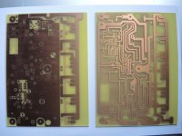
As promised yesterday, I've made the new PCB's two of them, double Sided, and these look good.
I have redone the whole process in production of PCB and I also found some negative spots where my production failed, several times.
Here I fully need to express my biggest Thanks to Jim Fahey, and the other guys, who pointed out what could be wrong back in July, when I just got Trash instead of nice looking PCB. And yes I saw that leftover in the right corner of Ground Plane, that it hasn't etched all, will correct that before drilling. need to check the PCB's anyway don't like to have time for a prolonged error spotting, like in the board before.
The Major problem was the Ultra Violet tubes, and secondly it was the Toner of the Printer which was old.
For the tubes, I need to preheat them for 15Minutes prior to expose the image on the PCB.
In the last couple weeks I have done several PCB and each are just good. Satisfying.
These in the picture, I have printed and developed yesterday, and etched just an hour ago.
Looking good to finally building the 6Paralell Output Transistor Version of the Class A Single End Amplifier, Even there is no need to do that all, but I wanted to know how much output Power I will get that way, when I full load it with 7.5 Ampere IDLE CURRENT. Need to make it switchable that I also can use the amp the same way it is now, meaning with just 3.8 - to 4 Amps Idle Current. the use for 8 Ohms Speaker, even all my speakers are below that, in the range of 3.5 - 4.1 Ohms. Just plain resistance..
Now the 2 PCB's will get drilled, then cleaned, then Polished, then protected against moisture, and after that I will assemble these. And hopefully it works as expected.
So I will be back as soon as I am that far. I will also write a Summary of what it takes to design and build an amplifier if all is DIY, but this will be at the end of this.
For the time being, you all please enjoy the last days of this rather "Complicated Year 2020" Thanks for reading
Chris Hess
Gentlemen,
Last day for Christmas Celebration here, tomorrow we need to go back to Office for another 4 days. But I think this is nothing than fair, happy that we are still around, and that we are able to work, and enjoy to be here on this site.
As promised yesterday, I've made the new PCB's two of them, double Sided, and these look good.
I have redone the whole process in production of PCB and I also found some negative spots where my production failed, several times.
Here I fully need to express my biggest Thanks to Jim Fahey, and the other guys, who pointed out what could be wrong back in July, when I just got Trash instead of nice looking PCB. And yes I saw that leftover in the right corner of Ground Plane, that it hasn't etched all, will correct that before drilling. need to check the PCB's anyway don't like to have time for a prolonged error spotting, like in the board before.
The Major problem was the Ultra Violet tubes, and secondly it was the Toner of the Printer which was old.
For the tubes, I need to preheat them for 15Minutes prior to expose the image on the PCB.
In the last couple weeks I have done several PCB and each are just good. Satisfying.
These in the picture, I have printed and developed yesterday, and etched just an hour ago.
Looking good to finally building the 6Paralell Output Transistor Version of the Class A Single End Amplifier, Even there is no need to do that all, but I wanted to know how much output Power I will get that way, when I full load it with 7.5 Ampere IDLE CURRENT. Need to make it switchable that I also can use the amp the same way it is now, meaning with just 3.8 - to 4 Amps Idle Current. the use for 8 Ohms Speaker, even all my speakers are below that, in the range of 3.5 - 4.1 Ohms. Just plain resistance..
Now the 2 PCB's will get drilled, then cleaned, then Polished, then protected against moisture, and after that I will assemble these. And hopefully it works as expected.
So I will be back as soon as I am that far. I will also write a Summary of what it takes to design and build an amplifier if all is DIY, but this will be at the end of this.
For the time being, you all please enjoy the last days of this rather "Complicated Year 2020" Thanks for reading
Chris Hess
Attachments
Last edited:
PID Circuit and how to.
Gentlemen,
As Promised here the Circuit of the PID or Servo Control I use to control the output Stage of my Class A Single End Amplifier.
Usually this Circuit works fine, I use this for more than 20 years, build it first time in late 90'.
its easy to adjust replacing only one Resistor = R211 to get faster or slower response.
Also a Adjustment Circuit can be build into that OP AMP if the user goes with OP 37E. then a Variable Resistor or just call it trimpot, 10K connects with Pin 1 & 3 to pin 1&8 of the OP amp and then Pin 2 connects to Rail Plus Voltage OP 37 it is PIN 7, and after that it is possible to adjust the output Voltage on Pin 6 of the OP AMP to 0.00000Volt or as much as it is desired.
What this PID does NOT change is:
1. Sound Quality
2. Gain of the Amplifier
3. Bandwidth of the Amplifier
4. Nor Input or Output Signal in anyway
The Pid is just an easy comparator of a given voltage at one point, and the corresponding Voltage at another point. if either one change, PID will Act and automatically correct it.,
The use is Easy also. if the Amp is one of this Runnaway amps, then after connected all wires of the pid to the Amplifier, it can also have it's own housing and PSU. Remove the IC from the PID Cirquit, so this means the builder has to use IC SOCKETS. then powerup the AMPLIFIER, wait a minute and then measure and adjust that you get 0.00 Volts at the output of the Amplifier, of course, either Loudspeaker or Dummy Load have to be connected and no Signal on the input. best is to lay the Input short to GND, use a RCA JACK and short out both Pins and then plug it into the female jack at the back of the amp.
As soon 0 volts has been adjusted, here the rule is the closer the better, switch off the Amp, Insert the OP AMP and then start up the amp and notice the speed which this PID will correct the DC OUTPUT VOLTAGE to 0 volts..
This will also work on AB amps and Amps with differential input.
Placing the Circuit, and also a Picture from a output Stage also Class A where I added this PID. It also compensates temp differences of the AMP.
In the Circuit I forgot to place R205, so this Resistor is missing.. Seems I'm a bad counter... Also, there is no R205, so don't ask.. It got lost somehow.. and I'm not going to rewrite the Circuit just because of an missing resistor.. LMAO, I just notice that right now.. hehehehehe
It will correct DC Voltages at the Output up to 2.5 Volts down to 0.!
Make sure the Rails of the PID are Regualted, and more than 15Volts +- if you want it to work perfect.
Regards
Chris Hess
Attachments
Last edited:
Happy New Year 2021 - it's about that Class A.
Gentlemen,
Everyone here on these Forums, a Happy New Year 20210, Good Health and a prosperous future. I wish you all the best for you, your family, and your daily life.
My, next step or extension Class A Single End Amplifier, Version 9.6.9, is ready and Tested alsmost to full.
9 For Version 9 - Last version was 8.5
6 because of 6 Paralelled Output Transistors.
9 because of between the Version which is in the BOX there are 11 or more Updates or small changes in the layout of the AMP, changes of Values from resistors, and a small change in the overall Circuit.
This is all to step up effiency and also Quality and flatness for the Sound, less Noise, Less Hum. And almost 0 DC in fact it is 0.0001 Volt to 0.0015 Volts, while operating the Amplifier. There is a slight increase in Heat, but it is no problem, neither in short or long Term of operating that Amplifier.
here is one of the new made motherboards, fully assembled and tested.
Bandwitdth is 10 Hz to 250Khz this with -3db @Full load of 15.1 Volts output @ a distortion Level of 0.1% over the full frequency band.
The Amplifier will be very linear within the range of 10 Hz - 150khz. it is within 0.2db.
As I'm not a Number Freak, this is more than good enough, as the sound is really Extremly good.
So the actual Listening Bandwidth, from 20 - 20khz there is nothing to expect more, everything is there, no wishes open.
It's Powerfull, it's soft as Silk, or a baby butt. It reflects the music as it is feed into it.
Tomorrow, I will get both sides ready and place the boards on the active heatsinks.
But just to give you a small glimpse at it, I place some pics of the newly assembled Boards here, please Note, Input Transistor is Plug an Play, so you don't need to look for it, as the transistor is in the second board at present time. Tomorrow I will find matching Input, drivers and output Transistors. I'm on it since 08.00Am this morning, and now it is 7pm here in Swiss, and don't forget, I'm an old man. So going to enjoy evening without soldering on that Amplifier. I still got 2 more days where I can work on..
The Final Circuit I will also place. BTW all Cicuits I placed here are working, and all are working good, there is just this little something inside of me, I think when I'm finish, oh this I could make better, and this is the reason for that amp. I call it the unfinished one, even it's boxed already and listening to it everyday.
I also will make some pics of each and every board I made, till I'm here where I am.. There are quite a few, have also some hardwired, when I started out.
Enjoy the first day of 2021, take care of your self, be carefull not to get into the way of Corona.
Thanks for Reading
Chris
Attachments
The Numbers
As I said, I'm not a number freak, but still, we need to take a look @ these..
Now I have tested one Side of the Amplifier today, for at least 6 hours.
Call it Burn in. Then I listened to it, and had to made a few changes to the Wattage of the Filter Resistors, as well as noise Caps at the first transistor.
Then I started the amp without PID, and adjusted it to output 0 DC Volts, plugged in the Mixer, which is fed by Turntable, hook up speakers even before I used the Function Gen to check the numbers. It was very pleasant.
Then I added the PID, and it just works like a dream.,
That's about the day today,. Now it's already almost 8 PM again in ten minutes. I'm Satisfied with it, it is better than I thought,noise and Hum are history as far I can measure that and as far I can trust my ear while sticking it into the Loudspeaker Cone, and it's just DEAD, no whatsoever, until there is signal at the input of the amplifier.
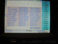
Numbers:
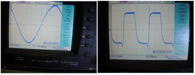
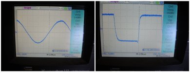
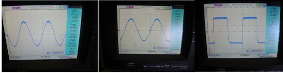
4hz Square Wave at full Load, into 4 Ohms
10Hz Sine & Square @full Load into 4 Ohms
1khz Sine into 4 Ohms
20Khz Sine & Square into 4 Ohms
50khz Sine & Square into 4 Ohms
100Khz Sine & Square into 4 Ohms
All numbers of the Scope it generates while measuring.
Heat of RE while testing something like 136Degrees Celsius
Heat of the Amplifer, using active Cooling to keep it as low as 62 Degrees Celsius
Line voltage @ +- 40Volts
AMP @ about 5.3 Amps
VDC output while full load, max 4.9mv standart 0.1 millivolt
Oh, of course I've got Pictures to show as well. Sorry Quality isn't that good as I actually whish the pics could be.
I do not further comment the amplifier, I also see what could be better, but then I have to say, I'm just an old man, not a professional, at all, so for this time that is the best I can do. But certainly there some fine Tuning will be done, even it's actually no need of..
If you see something misterious, or think something isn't the way it shows, I'm glad to answer your Questions.
If there is nothing which changes anything signifcant by whatever means, then there will be no follow up on this Post here.
What will follow is the Board design, outlines, Gerberfiles BOM and what else matters. Also the complete circuit used here, exactly as it is, and then a explanation how to manufacture this amp.
Otherwise, that's it then..
Have a line drive in my mind, also class a but not as hot as this one here..
Thanks for Reading
Chris Hess
January 2nd. 2021
As I said, I'm not a number freak, but still, we need to take a look @ these..
Now I have tested one Side of the Amplifier today, for at least 6 hours.
Call it Burn in. Then I listened to it, and had to made a few changes to the Wattage of the Filter Resistors, as well as noise Caps at the first transistor.
Then I started the amp without PID, and adjusted it to output 0 DC Volts, plugged in the Mixer, which is fed by Turntable, hook up speakers even before I used the Function Gen to check the numbers. It was very pleasant.
Then I added the PID, and it just works like a dream.,
That's about the day today,. Now it's already almost 8 PM again in ten minutes. I'm Satisfied with it, it is better than I thought,noise and Hum are history as far I can measure that and as far I can trust my ear while sticking it into the Loudspeaker Cone, and it's just DEAD, no whatsoever, until there is signal at the input of the amplifier.
Numbers:
4hz Square Wave at full Load, into 4 Ohms
10Hz Sine & Square @full Load into 4 Ohms
1khz Sine into 4 Ohms
20Khz Sine & Square into 4 Ohms
50khz Sine & Square into 4 Ohms
100Khz Sine & Square into 4 Ohms
All numbers of the Scope it generates while measuring.
Heat of RE while testing something like 136Degrees Celsius
Heat of the Amplifer, using active Cooling to keep it as low as 62 Degrees Celsius
Line voltage @ +- 40Volts
AMP @ about 5.3 Amps
VDC output while full load, max 4.9mv standart 0.1 millivolt
Oh, of course I've got Pictures to show as well. Sorry Quality isn't that good as I actually whish the pics could be.
I do not further comment the amplifier, I also see what could be better, but then I have to say, I'm just an old man, not a professional, at all, so for this time that is the best I can do. But certainly there some fine Tuning will be done, even it's actually no need of..
If you see something misterious, or think something isn't the way it shows, I'm glad to answer your Questions.
If there is nothing which changes anything signifcant by whatever means, then there will be no follow up on this Post here.
What will follow is the Board design, outlines, Gerberfiles BOM and what else matters. Also the complete circuit used here, exactly as it is, and then a explanation how to manufacture this amp.
Otherwise, that's it then..
Have a line drive in my mind, also class a but not as hot as this one here..
Thanks for Reading
Chris Hess
January 2nd. 2021
Attachments
-
 10. Numbers all of them.jpg221.1 KB · Views: 60
 -
 9. 100Khz Amp and VDC output.jpg306.2 KB · Views: 56
 -
 8. Sine & Square 100Khz.jpg395.7 KB · Views: 39
 -
 7. Sine & Square 50khz.jpg338.2 KB · Views: 41
 -
 6. Sine 1khz-Sine 20khz-Square 20khz.jpg461.3 KB · Views: 37
 -
 5. 10HZ.jpg239.5 KB · Views: 46
 -
 4. 4.2 HZ Square.jpg298.8 KB · Views: 53
 -
 3. Heat RE.jpg347.3 KB · Views: 42
 -
 2. Number PSU, HEAT, VDC OUT.jpg743.9 KB · Views: 43
 -
 1. Amp under Test.jpg230.2 KB · Views: 55
Last edited:
Why not try Mosfet for input, Yes here it is.
Guys, Hello,
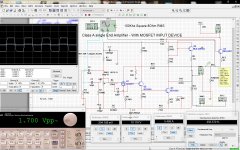
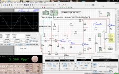
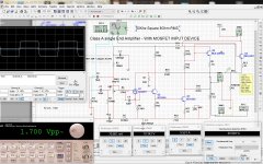
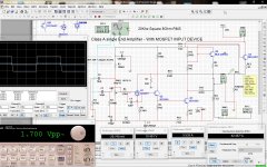
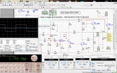
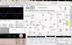
I wrote that if there isn't anything really significant, then I wouldn't post on this subject again. But there is something significant. I changed the circuit just a little bit, a few values of a few Resisitors, and then I went on and exchanged the first Transistor BC556B, to be a Mosfet. At present time it's only Simulation, but I'm positive that it will work out exactly that Way it shows in the following pictures.
I already ordered the Mosfets.. So as soon these arrive, I will test exactly that Circuit as you can see it in the pictures. It starts at 1KHZ including, RMS output @8 Ohm. then also THD, then also VDC out at the output, and this without SERVO. When RMS Square Wave my Progam I use to Spice, it will display a faulty Distortion percentage, just ignore it, the real is in the pictures of SINE WAVE.
For all mesurements
Sine Wave input is set to Peak to PEAK 3.3 VOLTS
Square Wave Input is Set to 1.7 Volt Peak to PEAK which equals the SQUARE WAVE 10.7 RMS Voltage and so which delivers finally the MAX OUTPUT AT 8 Ohm of this Amplifier which is about 25 Watts.
Any Question just ask.
Regards Chris Hess
Guys, Hello,
I wrote that if there isn't anything really significant, then I wouldn't post on this subject again. But there is something significant. I changed the circuit just a little bit, a few values of a few Resisitors, and then I went on and exchanged the first Transistor BC556B, to be a Mosfet. At present time it's only Simulation, but I'm positive that it will work out exactly that Way it shows in the following pictures.
I already ordered the Mosfets.. So as soon these arrive, I will test exactly that Circuit as you can see it in the pictures. It starts at 1KHZ including, RMS output @8 Ohm. then also THD, then also VDC out at the output, and this without SERVO. When RMS Square Wave my Progam I use to Spice, it will display a faulty Distortion percentage, just ignore it, the real is in the pictures of SINE WAVE.
For all mesurements
Sine Wave input is set to Peak to PEAK 3.3 VOLTS
Square Wave Input is Set to 1.7 Volt Peak to PEAK which equals the SQUARE WAVE 10.7 RMS Voltage and so which delivers finally the MAX OUTPUT AT 8 Ohm of this Amplifier which is about 25 Watts.
Any Question just ask.
Regards Chris Hess
Attachments
-
 8. Square 100Khz 8Ohm RMS.jpg363.5 KB · Views: 44
 -
 7. Sine 100Khz 8Ohm RMS.jpg365.2 KB · Views: 42
 -
 6. Square 50Khz 8Ohm RMS.jpg359.7 KB · Views: 32
 -
 5. Sine 50 Khz 8 Ohm RMS.jpg365.4 KB · Views: 35
 -
 4. Square 20Khz 8Ohm RMS.jpg363.8 KB · Views: 32
 -
 3. Sine 20 Khz 8 Ohm RMS.jpg364.3 KB · Views: 40
 -
 2. Square 1khz 8Ohm RMS.jpg363.5 KB · Views: 45
 -
 1. Sine 1Khz 8Ohm RMS.jpg365.6 KB · Views: 55
Last edited:
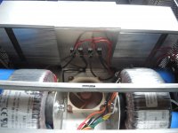
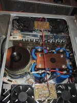
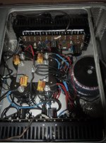
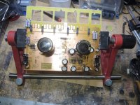
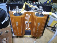
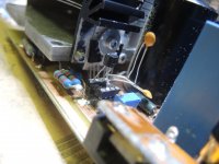
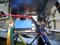
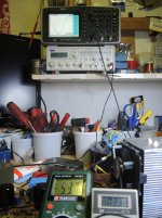
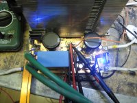
The Toroids are mounted on two Rubber Blocks, not connecting to each other.. both Bolts are in rubber molded, and do not have contact within the center of the toroid,. both are Floating..
Check out the picture,,
Is not finish yet but most is done, need to set the panel for left side, then Ventilation control and also the switchable 18 - 28 Watt Relays and Switches are not set yet.. but this ain't a problem parts are already build and all I need to do is to place them in the box..
I see you are using nylon locking bolts but if the bolts themselves are touching the metal brackets and the brackets are making electrical (metal/metal) contact with the chassis, you still likely have a shorted turn. It doesn't need to (nor should it ever) make contact inside the transformer.
See this thread for more explanation - BrianGT has a nice image on post#4
https://www.diyaudio.com/forums/parts/30676-toroids-mounting-bolts-shorted.html#post354646
Please don't take this as being disrespectful and I certainly hope my observation is incorrect but since this is being posted in construction tips, it needs to be safe and not mislead new builders. I just want to make a clarification.
Happy New Year and congratulations on a very nice 'from the ground up' project!
Cheers!

Hi
Happy New Year to you too.
Now these Bumpers are RUBBER, and the BOLT don't go through both end of the side Panels which are holding the Transformers. one side one BOLT. Between the Bolts there is about a 2 Inch or 5 Centimeter Air (Rubber GAP). Between the holders and the Transformer Windings itself there is also on both sides at least 1 CM more than a Quarter Inch AIR GAP.
Check out the link I place here, there you can see the System. Both aluminum plates which hold the transformers Make only contact VIA the CASE, but not THROUGH the Inner Circle (DONUT) of the Transformer in No Way the Transformer is floating on these two Rubber Bumpers. and no where the TRT touches the metal of the CASE.
Hope this explains it, at least I can't measure any Magnetic field or likewise, which would cause and problems.
here the link to this concern someone else brought up already some time ago.
Building a Class Amplifier from Scratch
But thanks for the roses, I just try to do somethings the otherway, around, not like the mainstream.
I'm happy that you and all others here who come to read my lines, come at all, and that you are interested at all, for whatever reason it might be.
I can honestly assure you that here it is of no concern to have any loop.
If it loops then switching on the amplifer it would take only a few minutes and the CENTER BOLT WOULD SMOKE OF HEAT, I have made that before already, here this is not the case, the only cold thing on that AMPLIFIER are the TRANSFORMERS and the Holders, everything else gets hot, and I mean up to almost 70 degrees Celcius.
BTW this amp runs everyday at least 5 hours, mostly it's more than that. but I can make a heat check on it,, the coming days, even I'm sure that it's no concern. AGAIN, between these two Bolts in the RUBBERS is a AIR GAP of 2 Inches and between the RUBBER is also an AIR GAP of more than a half Inch.. = 15mm. I mean in the middle of the Transformer hole there is just rubber and AIR, no Iron at all.. the same as the transformer would be free running without any brackest.
Regards Chris
Last edited:
 Air gap is
  genius! Thank you for clarifying!
Final Tests of Class A Single End Amplifier - 6 paralell Output Transistors
Hi Guys
So after a Week of testing the "Mosfet" Input as shown in my prior Post, I have to say, that this didn't work out as expected. I got very nices numbers while simulation, but the REAL WORLD Mesurements showed me that this ain't that easy. Even the Amp was Working quite well with that MOSFET at the input, sound wasn't that good. It lost livelyness, Sound clarity, it also lost Punch in the lower frequencies. It isn't that easy at all, but I'm working on it.
Oposite the latest PCB of the 6 paralell Output Version with transistor input. Works just fantastic.
So here a few Pics of Scope readout (Yesterday Morning 7 am) starting @ 1khz - 100Khz. Sine and Square also included Sound degration by distortion ( something like 0.15% at the full output).
So, also the other day I modified one of these Active Cooling Units, so it can take 6 Output transistors, and all will be cooled exactly the same, and this only with a Iron Saw, a File, a Drill and some Sandpaper.
Yesterday I gave that Prototype to a Metal Processing Factory to make this special 10mm thick Copper plate in Professionel manners.
Again it will take a while for this to finish and it's extremely Expensive.
But anyway I show you the prototype of this here, how the Active Cooling Unit looked prior and after the mods.
But I'm sill Working on that MOSFET input and as soon I get REAL WORLD RESULTS which I can accept then I will place the Circuit * already done in my prior Post* and if the Circuit changes then of course I will place the new circuit with all updates and changes here.
And here the explanation to the pictures.
I have made following tests.
All with Dummy Loads none Conductive.
Rail Voltages were 40.7 +-
RE 7.5Ohm
Measurents were done @ 69.9 Degrees Celcious, which is the max heat that Amp comes to.
Thanks for Reading updates will follow
Chris Hess
Hi Guys
So after a Week of testing the "Mosfet" Input as shown in my prior Post, I have to say, that this didn't work out as expected. I got very nices numbers while simulation, but the REAL WORLD Mesurements showed me that this ain't that easy. Even the Amp was Working quite well with that MOSFET at the input, sound wasn't that good. It lost livelyness, Sound clarity, it also lost Punch in the lower frequencies. It isn't that easy at all, but I'm working on it.
Oposite the latest PCB of the 6 paralell Output Version with transistor input. Works just fantastic.
So here a few Pics of Scope readout (Yesterday Morning 7 am) starting @ 1khz - 100Khz. Sine and Square also included Sound degration by distortion ( something like 0.15% at the full output).
So, also the other day I modified one of these Active Cooling Units, so it can take 6 Output transistors, and all will be cooled exactly the same, and this only with a Iron Saw, a File, a Drill and some Sandpaper.
Yesterday I gave that Prototype to a Metal Processing Factory to make this special 10mm thick Copper plate in Professionel manners.
Again it will take a while for this to finish and it's extremely Expensive.
But anyway I show you the prototype of this here, how the Active Cooling Unit looked prior and after the mods.
But I'm sill Working on that MOSFET input and as soon I get REAL WORLD RESULTS which I can accept then I will place the Circuit * already done in my prior Post* and if the Circuit changes then of course I will place the new circuit with all updates and changes here.
And here the explanation to the pictures.
I have made following tests.
All with Dummy Loads none Conductive.
Rail Voltages were 40.7 +-
RE 7.5Ohm
Measurents were done @ 69.9 Degrees Celcious, which is the max heat that Amp comes to.
- 1khz Sinewave @8Ohms 14Volts RMS, Less than 0.05 % Distortion, Input voltage 3.2 Volts P-P
- 1Khz Square wave @8Ohms 10Volts RMS, Input voltage 1.5Volts P-P
- 1Khz Sinewave @8Ohms just before clip *Negative side* @14.8V RMS Less than 0.08 % Distortion, Input voltage 3.5 Volts P-P
- 10Khz Sinewave @8Ohm, 14Volts RMS, Less than 0.05 % Distortion, Input voltage 3.2 Volts P-P
- 10Khz Square wave @8hms, 10Volts RMS Input voltage 1.5Volts P-P
- 20Khz Sine Wave @8Ohms, 14Volts RMS Less than 0.05 % Distortion, Input voltage 3.1 Volts P-P, should be 3.2 Sorry about that Input voltage differs, just saw this here when I would upload the file.
- 20Khz Square Wave @8Ohms Input voltage 1.5 Volts P-P
- 50Khz Sine Wave @8Ohms Distortion @ 0.15% , Input voltage 3.1 Volts P-P , should be 3.2 Sorry about that Input voltage differs, just saw this here when I would upload the file.
- 50Khz Square Wave @8Ohms , Input voltage 1.6 Volts P-P should be 1.5 Sorry about that Input voltage differs, just saw this here when I would upload the file.
- 100Khz Sine Wave @8Ohms Minus 0.56db, Input voltage 3.1 Volts P-P should be 3.2 Sorry about that Input voltage differs, just saw this here when I would upload the file.
- 100Khz Square Wave @8hm Input voltage 1.6 Volts P-P should be 1.5 Sorry about that Input voltage differs, just saw this here when I would upload the file.
- Noise @ the output Terminal LSP Out on the PCB = 0.48millivolts RMS, @1.5Mhz, with Input shorted to GND / Here I can try to get that lower and eliminate that 1.5MHz.I already did, last night, Will send the pics later
Thanks for Reading updates will follow
Chris Hess
Attachments
-
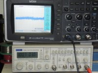 6. F. VDC =mv 1.5Mhz Input Short to GND-s.jpg233.4 KB · Views: 37
 -
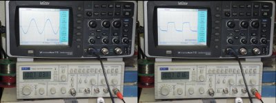 5. 100 Khz Sine - Square.jpg474.6 KB · Views: 32
 -
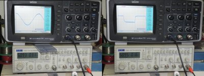 4. 50 Khz Sine - Square.jpg477.7 KB · Views: 36
 -
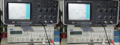 3. 20 Khz Sine - Square.jpg491.8 KB · Views: 41
 -
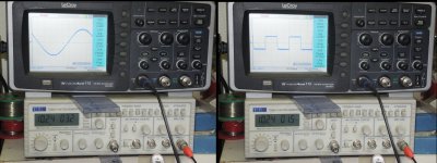 2. 10 Khz Sine - Square.jpg491 KB · Views: 39
 -
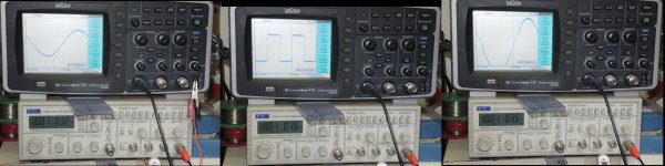 1. 1khz Sine-Square.jpg743.1 KB · Views: 43
 -
 PCB Mounted on Heatsink.jpg216 KB · Views: 43
 -
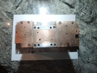 Modified 6 Transistor Version G5 Heat Sink.jpg181.3 KB · Views: 44
 -
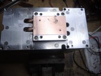 Original Active Heatsink G5 MAC Intosh.jpg155.2 KB · Views: 43
Last edited:
another in finalizing that CLASS A SINGLE END AMP
Good day everyone, everybody
It's Sunday again, my time to work on the Second Last Active Cooling Version of that Single End Class A amplifier.
Even that Amp actually has been build, and in the meantime has run over 1000Hours, since October, when I boxed it. It's just part-wise finished, because my goal was not only 2 output Transistors but 6 of them per Side.
Then also my goal was less heat on the AMP itself, not talking about these RE which still cross the 100degree Mark.
My goal is far more than this, and therefor it has to be done Step by Step.
So and this is the next step in the line which will be finished in about 1 month. For Active Cooling.
I have a Metal Manufacturer making these Copper Plate Extensions for the Heat Dissipation. 4 pieces cost me 350 Swiss Francs, which is the equivalent of 350USD, without the COPPER itself, just the work, copper I bought for 200Swiss,.!
The Copper Cooling Extensions for these 6 Transistors, which at present time are made on my Workbench, by hand, a Drill, a Metal File, and much of patience I already have shown in the last Post.
Then one more will follow, and only one and this is the same AMP with PASSIVE Cooling, have a Swiss Company make special HEAT-SINK size
L: 400mm or 15.7"
H: 200mm or 7.8"
W: 100mm or 3.93"
Thus will be finished in the next coming 3 months, as I Ordered only 5 Pieces, for 2and a half amplifier, the half one has it's own reason.
A few Pictures of both Sides of the New build Amps, with testing for 2nd, Harmonic order distortion, and the ones above. Please Note: Second Order Distortion has been MULTIPLIED by 10X just to view the curves better than on 1x..
Thanks for Reading, more is in the pipeline, but I have other work as well.
so hang on there,.
Thanks to all and Respect,
Special Thanks and Respect to the MASTERS here on this Forum for their Support.
Regards & Respect
Chris Hess
Attachments
-
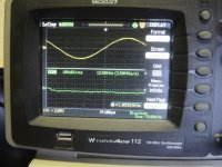 9. distortion @1Khz into 8Ohms 1Watt- ns-100dbvrms.jpg221.3 KB · Views: 41
 -
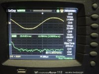 8. Distortion @1Khz 8Ohms Full Load- ns. 20dbvrms.jpg225.6 KB · Views: 38
 -
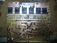 7. Placing Output Transistors.jpg223.8 KB · Views: 37
 -
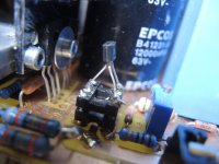 6. Seletable Input Device - Mosfet here.jpg138.8 KB · Views: 42
 -
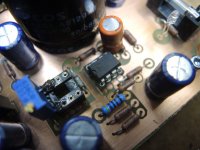 5. DC Adjustment of OP37E.jpg151.1 KB · Views: 43
 -
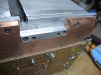 4. Added 10mm Copper Plate for Heat Dissipation.jpg155.6 KB · Views: 36
 -
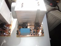 3. Right Side Class A Single End - 6 Output Tranisistors.jpg162.9 KB · Views: 42
 -
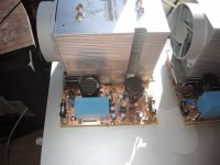 2. Left Side Class A Single End Amplifier - 6 Output Tranisitors.jpg164 KB · Views: 52
 -
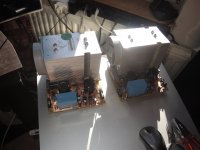 1. Class A Single End Amplifier - almost ready to place in the Box.jpg150.5 KB · Views: 59
 -
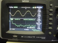 10. Distortion @100Khz into 8Ohms Full Load-ns -10dbvrms Full load.jpg892.2 KB · Views: 43
Last edited:
- Home
- Design & Build
- Construction Tips
- Building a Class Amplifier from Scratch