Hi everyone here..
I'm new here.. see my introduction then you know..
Building a Class A Amplifier from scratch.
Answering following Questions before you start. Here I talk about YOUR IDEA, not a design someone else posted on the net, or you find a finished circuit in some Magazine or likewise.
Questions should be as follows
1. Why Class A
2. How much can you spent on it
3. Are you conform with what it takes to build an Amplifier, never mind the class?
4. What the specs of the amp should be?
5. do you have the necessary tools to build it.
6. Do you have the necessary Computer Design and Simulation programs?
7. How about your technical knowledge?
8. Do you know how Class A operates versa Class B & Class AB - not Talking about the rest of Amps.
To build a decent amp, you need to be able to simulate and go beyond the regular designs. Today many Class A are sold which are in fact just AB amps BIASED with A Bias.
For me there are two Kind of Class A.
1. Single End Class A = this is an Amplifier where one Transistor per Stage making all the Work. Meaning amplifying the whole 360 degrees of the signal.
2. Push Pull where one Transistor amplifies the Signal and the Second one is the Current Source which enables the "Signal Transistor" to Work freely
The difference between Class A and Class B, respectively Class AB is, that a Class A Amp does not break the signal in two pieces.. Upper and Lower Signal
Class A is the only Amp where Distortion is the at minimum, where heat doesn't matter like in other configuration regarding Signal amplification, this only when the amp is designed well and the Working point of the Transistor is exact in the Middle of the Working field of that Transistor.
That the Sound of it is more close to the Natural Sound what you hear everyday. that the Amp reproduces the sound without coloring it.
The disadvantage is that you loose about 80% of the power. So if you have a Class A Single End Amplifier and you have a power supply with 0 + 50 Volts then the max Power you can expect to hear out of the Speaker are about 17 - 20 Percent. this means that you will get an RMS Voltage at the output of 10 Volts in the best case and only 8.5Volts in the NORMAL CLASS A Amplification scenario. So if you use Single End, then you are lucky if you get this 10 volts out, this would mean that you have about 12.5 Watts RMS @8Ohm, not yet looking at the Distortion which might occur because of so many reason like Components, layout of the PCB, Supply Voltage, etc etc.
Knowing all this I'm still going for Class A. Because if you really seriously do your job and giving your Best, consult the big guys if you get stucked, then success will be on your side. Then the next part of the story is what you do about the HEAT of a CLASS A. As the Amp burns Power away more than its able to deliver to the speaker..
In the days to come I will place some Schematics, PCB layouts and Building "instructions" which are necessary if you want to build a Class A.
Building Class A Amps you need to be able to Jump over you Shadow in sometime building something where all the world would say: na this never works.. but if you believe in what you do then I'm Sure that success is on your side. This is a small example. If anyone likes to see how the Amp looks like inclusive Specs and everything, then just ask. Developed by me. There is one resistor R2 10Ohm, its 200Watt.. the rest is all regular. this config has an output of about 12.5 Watt @8Ohm linear 10 -100Khz with very low distortion below .01 Linearity is +- 0.2 db over full bandwidth..
BTW I'm open for everything and with everything I mean I also can take Critics and all what comes with it.. Just let me know
Thanks for reading
Regards Chris
http://www.hecco.ch/pictures/class_a_amps/Class A - Double Stage Single End OP37 Amplifier.pdf
Last edited:
> Developed by me.
Are you claiming "invention"?
The idea has been around since the 1960s. I've done it with a resistor-load, but efficiency is few-% at best, optimum supplies are not balanced, and linearity is poor. I can't find my notes on that.
With your opamp on +/-22V, 10r and 8r, you can't get 8.88Vpk 6.3Vrms before clipping.
> two Kind of Class A.
There are MANY kinds of class A audio amps.
D.Self argues convincingly that a properly biased AB BJT is lower THD than any other amplifier.
Attachments
No
Hello
Thank you for your response.
No, I do not claim invention. BTW development and invention are two different things. At least in German, French Language and understanding and if this isn't like that in English then I'm sorry, my BAD.
I'm here to learn and give my knowledge further if this is OK with you. But sure I'm not here to discuss nonsense.
I would have a lot of Questions to you and the Circuit you presented is impressive. Now my build are not on the same level as yours.
I'm not satisfied when I get only 6.*** volts out of an Amplifier which I feed +-37 Volts or more into. And I will do anything to change that as long it is in my financial power.
First of I will download the Datasheet of the components I'm going to use.. and then read them through fully and after that I will use my Computer Program which is BTW National Instruments Circuit Design 14 or call it MultiSimm14 .
Then I will bring down my thoughts into that Program and calculate what is possible and what not. IT'S very hard to cheat that program and I'm for one far off from cheating in Circuits or on the results, because the only one I would cheat, is myself.
So far so clear I hope. I also know the rules of OHM. Also I know the CLASS A Rules and what can be done and what not. Also can read Resistor Colors. Reading a Scope whatever Brand and also Digital and Analog Multimeters.
Specs of Operational AMP OP37E & OP37GPZ ( Texas Instruments) I use, both of them (price per piece 5USD and more) Voltage P-P @22Volts Rail +- is 13.5 Volts. this is 9.5445 Volts RMS.
Let the Facts Talk:
http://www.hecco.ch/chris_hess_class_a_amps_2020.pdf
Enjoy weekend as I do..
anything else you might want to know sounds suspicious to you, Just ask.
Regards Chris Hess
Regards Chris Hess
> Developed by me.
Are you claiming "invention"?
The idea has been around since the 1960s. I've done it with a resistor-load, but efficiency is few-% at best, optimum supplies are not balanced, and linearity is poor. I can't find my notes on that.
With your opamp on +/-22V, 10r and 8r, you can't get 8.88Vpk 6.3Vrms before clipping.
> two Kind of Class A.
There are MANY kinds of class A audio amps.
D.Self argues convincingly that a properly biased AB BJT is lower THD than any other amplifier.
Hello
Thank you for your response.
No, I do not claim invention. BTW development and invention are two different things. At least in German, French Language and understanding and if this isn't like that in English then I'm sorry, my BAD.
I'm here to learn and give my knowledge further if this is OK with you. But sure I'm not here to discuss nonsense.
I would have a lot of Questions to you and the Circuit you presented is impressive. Now my build are not on the same level as yours.
I'm not satisfied when I get only 6.*** volts out of an Amplifier which I feed +-37 Volts or more into. And I will do anything to change that as long it is in my financial power.
First of I will download the Datasheet of the components I'm going to use.. and then read them through fully and after that I will use my Computer Program which is BTW National Instruments Circuit Design 14 or call it MultiSimm14 .
Then I will bring down my thoughts into that Program and calculate what is possible and what not. IT'S very hard to cheat that program and I'm for one far off from cheating in Circuits or on the results, because the only one I would cheat, is myself.
So far so clear I hope. I also know the rules of OHM. Also I know the CLASS A Rules and what can be done and what not. Also can read Resistor Colors. Reading a Scope whatever Brand and also Digital and Analog Multimeters.
Specs of Operational AMP OP37E & OP37GPZ ( Texas Instruments) I use, both of them (price per piece 5USD and more) Voltage P-P @22Volts Rail +- is 13.5 Volts. this is 9.5445 Volts RMS.
Let the Facts Talk:
http://www.hecco.ch/chris_hess_class_a_amps_2020.pdf
Enjoy weekend as I do..
anything else you might want to know sounds suspicious to you, Just ask.
Regards Chris Hess
Regards Chris Hess
+/-22V is really pushing the opamp supply, +/-19V is a more realistic range to choose to reliable long term operation.
There's not much point having the main supply much larger than the driver supply, all that does is waste more power and generate more heat.
The feedback network is rather high impedance, why not use 10k/1k and get less noise?
The amp isn't strictly class A because the NE5534 output stage is class B internally. You can bias it externally with several mA of pull-down current to force the output stage to class A. Arguably the output transistor already does this, but you'd need to check that's the case.
There are ways to bootstrap an opamp to track the signal and be a floating driver, which might be worth persuing for such a design to give more voltage swing and power. At higher power the opamp is going to struggle to deliver enough current unless a driver transistor is added.
Sorry I was in a hurry this morning when I read your comment.
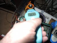
Anyway as you see in the pictures it is possible to get as much as 12.25 volts RMS out if Rail is 22 Volt or more.. With more I mean going 10% over the maximum Rating of the IC.. it doesn't kill the IC nor does it any bad as I can see. So the Voltage I apply to OP37 as well as the NE5534 is 23.60Volts + and 23.60Volts -. Speaking for the OP37E gets a better sound but less Output Level as the NE5534.
I have build many amps in my past 30 years, just for fun not for Sale. Here at home in Switzerland, I still have a Forte Audio A100 - Threshold - Speaking about that amp then the designer is the same as First Watt or Pass Labs.. Nelson Pass.
I spend a lot of my personal Money to buy amps in these 28 Years which I lived in Asia. I had a Threshold and many others also some Valve amps.
But I wanted to build my own. So I'm still on it..
This what you see is just a part of a project I'm trying to achieve. Nothing more nothing left. Use Google to find Single End Class A and you will not find a Class a with a IC in front nor with dual voltage. I have build several Transistor Class A.. Show you one here..
Usually I build every two or three years a new Amplifier just to proof to myself that I still have the patience to sit down and calculate thinking about the design.etc etc. I'm almost 70 and so I have another 2 years before I will stop and return to my second home in Thailand, and will stay away from public, just enjoy the last years of my life,
Now I'm still have that drive to try something new to me. Anyway my goal is this project I'm working on to have a Class A with on or two Tubes at the input and then Single end Transistor output. without C-Coupling as fas as possible and of course no Coupling transformers..So this Class A I have showed are just to find out what way I need to go.. I do not intend to use Mosfets or Fets..
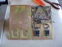
OK a few Pics will follow.. this is the PCB of Version 7 created sometime in September in 2017. its A single end Class A from Input to output. Idle or Bias is 2.5 amps at+- 48Volts
According my measurements its deliver 50 Watts@8 Ohm over a bandwith of 10 - 100K.
Input is similar to many amps in the open, single transistor. I use a PID to control DC at the output.
First pic is the PCB in two variations. Designed by ME
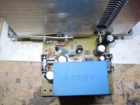
Following pics is the Amp itself and the Preamp American Made
http://www.hecco.ch/chris_hess_class_a_amps_2020_01.pdf
Anyway as you see in the pictures it is possible to get as much as 12.25 volts RMS out if Rail is 22 Volt or more.. With more I mean going 10% over the maximum Rating of the IC.. it doesn't kill the IC nor does it any bad as I can see. So the Voltage I apply to OP37 as well as the NE5534 is 23.60Volts + and 23.60Volts -. Speaking for the OP37E gets a better sound but less Output Level as the NE5534.
I have build many amps in my past 30 years, just for fun not for Sale. Here at home in Switzerland, I still have a Forte Audio A100 - Threshold - Speaking about that amp then the designer is the same as First Watt or Pass Labs.. Nelson Pass.
I spend a lot of my personal Money to buy amps in these 28 Years which I lived in Asia. I had a Threshold and many others also some Valve amps.
But I wanted to build my own. So I'm still on it..
This what you see is just a part of a project I'm trying to achieve. Nothing more nothing left. Use Google to find Single End Class A and you will not find a Class a with a IC in front nor with dual voltage. I have build several Transistor Class A.. Show you one here..
Usually I build every two or three years a new Amplifier just to proof to myself that I still have the patience to sit down and calculate thinking about the design.etc etc. I'm almost 70 and so I have another 2 years before I will stop and return to my second home in Thailand, and will stay away from public, just enjoy the last years of my life,
Now I'm still have that drive to try something new to me. Anyway my goal is this project I'm working on to have a Class A with on or two Tubes at the input and then Single end Transistor output. without C-Coupling as fas as possible and of course no Coupling transformers..So this Class A I have showed are just to find out what way I need to go.. I do not intend to use Mosfets or Fets..
OK a few Pics will follow.. this is the PCB of Version 7 created sometime in September in 2017. its A single end Class A from Input to output. Idle or Bias is 2.5 amps at+- 48Volts
According my measurements its deliver 50 Watts@8 Ohm over a bandwith of 10 - 100K.
Input is similar to many amps in the open, single transistor. I use a PID to control DC at the output.
First pic is the PCB in two variations. Designed by ME
Following pics is the Amp itself and the Preamp American Made
http://www.hecco.ch/chris_hess_class_a_amps_2020_01.pdf
Yes - Your completely right.
+/-22V is really pushing the opamp supply, +/-19V is a more realistic range to choose to reliable long term operation.
There's not much point having the main supply much larger than the driver supply, all that does is waste more power and generate more heat.
The feedback network is rather high impedance, why not use 10k/1k and get less noise?
Thank Your for your Input. it's appreciated.
This is CLASS A Single End output, with no " CURRENT SOURCE TRANSISTOR"other rules apply.
Take at the best 20% of the Line voltage or Rail voltage and then the Amp Clips. It's about 17% in reality, but the sound is more lively than with using a Current Source Transistor. I have several Current Source Class A
37 + 37 : 17% = 14.8 only so the 15Volts RMS can be schieved.
We have a saying in Swiss, a Class A Amp which don't heat up isn't a class A. And here nobody touches it.. My Wife stays two meter away from the amp..
Another one I build was up to 140C.. nothing happen to it. it was running for hours like that. This was 7 years back as I build that one.. still running perfect till today. Rail voltage 48Volts +-
I have about 10 or 12 self made Class A here at home, and another 5 in Thailand in my second home.. I'm Swiss, Wife is Thai. Owing a Thai Restaurant here in Swiss. This is just for fun.
If you read my follow up this is part of a project of me. I like to achieve the impossible.This is only the start.
I just finished calculations for full transistor with single end wait I let you guys see soon.. Layout is finished already.
As always I use a PID (proportional-integral-derivative controller) to keep DC at the Output under control.. you can also call it Servo or whatever.
It doesn't matter how it is called, it matter that it keeps 0Volts DC at the Output.. Besides that it will run and work without the SERVO very well at least in multisim 14.
Yes about the Feedback Network I will try that, thanks for the input
About the IC-OP37 Texas Datasheet give max 22. the NE5534 isn't the problem.. It's the OP37 which just delivers a little bit to little for me.. I wish to have 15Volts RMS this would equal 26 Watts - 28 Watts depending on the Distortion level which should be achieved..You know, a good Amplifier deosn't need to be turnet up all the way, because it will sound excellent on low output level already.. I seldom listening loud.. protectiing my ears is worth much more..
Talking about distortion everything under .5% cant be heard by Human as Studies from Germany showed some times ago.. they even were talking about 2 %
If you are looking at the specs of First Watt F7 then you know what I'm talking about even Nelson Pass check this 2% mark at 4 ohms
So it actually doesn't matter if its between 0.001 and .1
Thanks again for your Input, and Input is welcome.. positive or negative.. doesn't matter, because important is to hear what other people say.. it's always some truth in it, it's always a Win win Situation.. I'm proud to be here..
Here is a JLH 1996 class A amplifier i came across.
Didnt quite work when I built first one but works now.
Didnt quite work when I built first one but works now.
An externally hosted image should be here but it was not working when we last tested it.
@nigelwright7557
Yes, thank you very much. Looks really good..
There ain't be problem with the Amplifier I Build. It works, all what I do now, is just perfecting it. If you read my last post then you see my goal I set myself. This Amp the Single end Class A with Op37 as input and driver, is only the first step to get the limits close up.
Building electronic devices I go always for the maximum, there is nothing like " OK that's good enough" this sentence is not used.
@ Mark Tillotson I changed the Value of the feedback resistors, the way you mention.
Outcome. NE5534 is now more Linear than before max output RMS of the Amp with 8ohm load is 11.20Volts up to about 70Khz starting at 10 Hz.
As for the OP37E and OP37GPZ the output still not reaches the "announced level" of Texas instruments" Now its not a big thing.. But because of your input about the Network, I found a error in the PCB layout. the RAIL to BASE of the MJL4281 is definateley to "Long and also to close to collector Rail" so that this Oscillate on the Base of the POWER OUTPUT Transistor. But only whit the OP37, this don't count for the NE5534. If I reduce the Impedance of the Feedback more that I already have, then I fear that I loose the spirit of the Amp, meaning that it will sound dry. so now I stop that one, because it maxed out already.
Tomorrow I will manufacturer the PCB with the transistor and then a second one where I use a Emitter switch to increase Voltage Gain by 100% this means that the OP37 then only needs to amplify 50 % of now, instead of 11.5 volts. 5 - 6 volts are enough.. but as I already wrote, the transistor PCB with Class A from input to output comes first.
Earls in the morning will get that PCB done. I hope that I can test tomorrow afternoon.
I let you know..
Thanks at everyone.. This will be a LOOOOOOOOOOOOOONG journey..
The difficulty will come when I start the TUBE PART.. I never ever have build a Tube..
I will place all Layouts and Circuits online here as soon I can be sure that in long
term they don't fail.
Guys it 0:30 Am in Swiss, time to sleep for an OLD man.
See ya Happy Sunday
Chris
but the sound is more lively than with using a Current Source Transistor.
It is even more lively when instead of a resistor a choke load is used. Power and efficiency also go up. This choke will perhaps work well in your circuit
http://www.lundahl.se/wp-content/uploads/datasheets/2733.pdf
> instead of a resistor a choke load is used. Power and efficiency also go up.
Yes. Choke loaded efficiency "can" approach 50%. CCS-loaded, 25%. Resistor loaded, 8.5% (8.5786438...%).
But then it becomes a very different amplifier. Bias current can be very hard to control. We can't buy a perfect choke so there is some DC on the speaker.
Yes. Choke loaded efficiency "can" approach 50%. CCS-loaded, 25%. Resistor loaded, 8.5% (8.5786438...%).
But then it becomes a very different amplifier. Bias current can be very hard to control. We can't buy a perfect choke so there is some DC on the speaker.
Step two in my Project to Create a Class A from Scratch
Guy thanks for input.. I just finished to make the board of the next step Version.. Still with a big *200Watt or more* RE.
But opposite to the schematic with the OP37 it's full trasistorized..
Since its from beginning on Class a, and it doesn't have a Current Source Transistor, its very hard to control, and I like to build amps with at least parts as possible..
So I use a PID to help control DC at the Output. It can be run without as well just pulling the IC and adjusting 0 Volt if needt.. thats it.. Tomorrow we will know, will apply Power this evening..
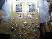
have some pics for you / tested only in Multisimm but version PCB old was tested in realtime and thats wha I had to make a new one.. and this I have to modify as well as Some Parts are to close to each other.,.
Using these Heat Sinks, I can save 8 transistors, it Generates less Heat * transistor only) and it's 75% less in weight. and this with almost the same Power . this one has a BIAS of 3.7 Ampere/
Guy thanks for input.. I just finished to make the board of the next step Version.. Still with a big *200Watt or more* RE.
But opposite to the schematic with the OP37 it's full trasistorized..
Since its from beginning on Class a, and it doesn't have a Current Source Transistor, its very hard to control, and I like to build amps with at least parts as possible..
So I use a PID to help control DC at the Output. It can be run without as well just pulling the IC and adjusting 0 Volt if needt.. thats it.. Tomorrow we will know, will apply Power this evening..
have some pics for you / tested only in Multisimm but version PCB old was tested in realtime and thats wha I had to make a new one.. and this I have to modify as well as Some Parts are to close to each other.,.
Using these Heat Sinks, I can save 8 transistors, it Generates less Heat * transistor only) and it's 75% less in weight. and this with almost the same Power . this one has a BIAS of 3.7 Ampere/
Attachments
Step two in my Project to Create a Class A from Scratch
Guy thanks for input.. I just finished to make the board of the next step Version.. Still with a big *200Watt or more* RE.
But opposite to the schematic with the OP37 it's full trasistorized..
Since its from beginning on Class a, and it doesn't have a Current Source Transistor, its very hard to control, and I like to build amps with at least parts as possible..
So I use a PID to help control DC at the Output. It can be run without as well just pulling the IC and adjusting 0 Volt if needt.. thats it.. Tomorrow we will know, will apply Power this evening..
have some pics for you / tested only in Multisimm but version PCB old was tested in realtime and thats wha I had to make a new one.. and this I have to modify as well as Some Parts are to close to each other.,.
Using these Heat Sinks, I can save 8 transistors, it Generates less Heat * transistor only) and it's 75% less in weight. and this with almost the same Power . this one has a BIAS of 3.7 Ampere/
Nice build(s), thanks for postingHi everyone here..
Building a Class A Amplifier from scratch.
")
Ok Amp has been powered on here the pictures..
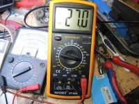
Rail voltage dropped from 38 to 27 volt wile using RE = 6 Ohm .
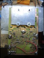
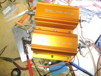
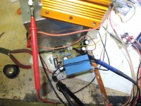
Tomorrow I will change the Transformer because this one is only 300VA getting the 500VA or even better the 750VA ... now I need to order Big Resistors in first place because 6 Ohm draws a mere 8 Ampere.. But they do not have 8 Ohm so I need to order 2x15Ohm and the combinde parallel. But better you guys take a look at the pics from just a while ago.. THIS IS A PURE CLASS A.. three stage.. = Input BC556, Drive BD139-16 and output MJL4281 - the IC is used as PID and can be removed, the amp certainly still works without flaw.. But with PID the DC at the output is only a few *0- 20 Millivolts. If the PID has been removed the ist about 50 + to 50 - Millivolt DC at the output..
Thanks for Reading
IF the Amp is finished that it runs stable for 24 hours, this meaning its a real hard test, then I will place all of the DATA which are needet to build the AMP here.. The only expensive components are the Input capacitor approximatley 12 USD /Piece and RE 200 Watt 20 USD /Pieces.. as the builder can save money on the heatsinks, *mine are from Mac G5* and on the ttransistors because it takes two only where with regulat heatsinks it would need then of them.
Hope you like the pics..
Placing the LAYOUT AS WELL.
Rail voltage dropped from 38 to 27 volt wile using RE = 6 Ohm .
Tomorrow I will change the Transformer because this one is only 300VA getting the 500VA or even better the 750VA ... now I need to order Big Resistors in first place because 6 Ohm draws a mere 8 Ampere.. But they do not have 8 Ohm so I need to order 2x15Ohm and the combinde parallel. But better you guys take a look at the pics from just a while ago.. THIS IS A PURE CLASS A.. three stage.. = Input BC556, Drive BD139-16 and output MJL4281 - the IC is used as PID and can be removed, the amp certainly still works without flaw.. But with PID the DC at the output is only a few *0- 20 Millivolts. If the PID has been removed the ist about 50 + to 50 - Millivolt DC at the output..
Thanks for Reading
IF the Amp is finished that it runs stable for 24 hours, this meaning its a real hard test, then I will place all of the DATA which are needet to build the AMP here.. The only expensive components are the Input capacitor approximatley 12 USD /Piece and RE 200 Watt 20 USD /Pieces.. as the builder can save money on the heatsinks, *mine are from Mac G5* and on the ttransistors because it takes two only where with regulat heatsinks it would need then of them.
Hope you like the pics..
Placing the LAYOUT AS WELL.
Attachments
-
 i.Voltage Drop.jpg270.7 KB · Views: 80
 -
 h.Sine Wave 46K.jpg125.2 KB · Views: 86
 -
 g.Sine Wave 10K.jpg127.1 KB · Views: 74
 -
 f.Sine Wave 5k.jpg136.5 KB · Views: 88
 -
 e.Sine Wave 1k.jpg119.7 KB · Views: 99
 -
 d.Readout DC VOLTAGE Outpout full load.jpg272.4 KB · Views: 100
 -
 c.Outputswing & DC Current-Ampere Rail.jpg229 KB · Views: 126
 -
 b..RE 400 Watt.jpg185.6 KB · Views: 118
 -
 a..Amp Top.jpg233.8 KB · Views: 354
 -
Class A Layout full transistor output with PID-PCB.pdf149.2 KB · Views: 88
So this late afternoon & evening and evening I took some hours to work on that Transistor Class A.. I had a big problem with the input Transistor, each time when I shorted it to GND it blew the Transistor. Or if I changed Input Cables without switching off the Amp, Next thing I knew was Transistor complete short.. anyway someone can imagine..
Since last Sunday when I made the layout for the PCB I needed to change some lines, because I couldn't place a Resistor the way I wanted. So I moved the input line from 40UF Cap away, no I just deleted the line,.,. and afterwards I forget to redraw. When I started the Amp, I had no sound .. after a few minutes I found the missing line, or at least where the line should be.. Ok a wire will do as well for test. Now the second Culprit started.. I soldered the wire at the input terminal before the Cap.. instead behind.. and this was enough to cost me lots of sweat.. no change in anything meaning stability or Sound or like that.. just blew the transistor when Shorting the Input for testing..
After I found this everything is working neat and clean.. Good Sound.. very natural, lots of strength, fast in reproducing the sound. Changed 500VA Transformer and changed the RE resistor to 7.5 ohm instead of 6.
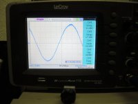
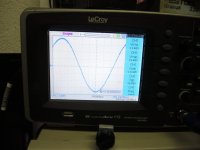
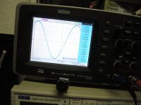
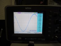
Took voltage down to 35Volts +- . Now I have 13.8 Volts with Sine Wave from 10 - 100k before clipping and with less than *POINT* .2 % Distortion * My scope has this function to measure* Also Phase differs about 3 degrees between 10Hz - 100Khz. but this is because I had to cancel noise on the Input transistor as well as on the Drive transistor.. DC is very Stable max +20millivolts - 18millivolts.. Tested into 8 Ohm also 4 ohms..
Next step is 24 hour real run with loudspeaker.
On that two hour run from this evening the heating of the transistors was relatively low 50C max 55C. the fan which makes the active cooling turns at 380RPM its rather noiseless.. The 200Watt Resistor get's about 90C screwed onto a Anodized HEAT SINK 15cm X 15cm by 5cm latter one is thickness..
So if this goes into a Case then the Resistors will be doubled, meaning 400Watts Per Channel *2x200*, screwed on the back of the Amp but the Resistor will stay inside. this gives then a Air circulation Because the Fans of the Amp will be forced to get Air from surrounding of the Amp and then directed blowing from the output which already has been cooled onto the 400 Watt Resistor then leaving the case and cooling the Heat sinks of the RE.
Since the heat sinks are on the outside of the case, protected by some Wire-mesh to cover the sinks, so it's not touchable will generate Airflow.. and everything will be fine..
since the case is rather large, I will try to place a second Pair of a CLASS A in the Same case.. the one with the Tubes.. But this is far away as I have never done anything with tubes..Soon I get the schematic online..
Acknowledgement:
The Input of that Class A was designed by Scott Elliot, I use some part of that Input or better say the idea behind that input of Scott Elliot Australia in that Amplifier. The stages after are my own Development and design. Thanks to Scott.
When I upload the source Schematic of this Amplifier, the input section, which was designed by Scott Elliot will be marked in an other Color.. and mentioned.. even its only a few resistors and a ZD
Thanks for Reading..
Since last Sunday when I made the layout for the PCB I needed to change some lines, because I couldn't place a Resistor the way I wanted. So I moved the input line from 40UF Cap away, no I just deleted the line,.,. and afterwards I forget to redraw. When I started the Amp, I had no sound .. after a few minutes I found the missing line, or at least where the line should be.. Ok a wire will do as well for test. Now the second Culprit started.. I soldered the wire at the input terminal before the Cap.. instead behind.. and this was enough to cost me lots of sweat.. no change in anything meaning stability or Sound or like that.. just blew the transistor when Shorting the Input for testing..
After I found this everything is working neat and clean.. Good Sound.. very natural, lots of strength, fast in reproducing the sound. Changed 500VA Transformer and changed the RE resistor to 7.5 ohm instead of 6.
Took voltage down to 35Volts +- . Now I have 13.8 Volts with Sine Wave from 10 - 100k before clipping and with less than *POINT* .2 % Distortion * My scope has this function to measure* Also Phase differs about 3 degrees between 10Hz - 100Khz. but this is because I had to cancel noise on the Input transistor as well as on the Drive transistor.. DC is very Stable max +20millivolts - 18millivolts.. Tested into 8 Ohm also 4 ohms..
Next step is 24 hour real run with loudspeaker.
On that two hour run from this evening the heating of the transistors was relatively low 50C max 55C. the fan which makes the active cooling turns at 380RPM its rather noiseless.. The 200Watt Resistor get's about 90C screwed onto a Anodized HEAT SINK 15cm X 15cm by 5cm latter one is thickness..
So if this goes into a Case then the Resistors will be doubled, meaning 400Watts Per Channel *2x200*, screwed on the back of the Amp but the Resistor will stay inside. this gives then a Air circulation Because the Fans of the Amp will be forced to get Air from surrounding of the Amp and then directed blowing from the output which already has been cooled onto the 400 Watt Resistor then leaving the case and cooling the Heat sinks of the RE.
Since the heat sinks are on the outside of the case, protected by some Wire-mesh to cover the sinks, so it's not touchable will generate Airflow.. and everything will be fine..
since the case is rather large, I will try to place a second Pair of a CLASS A in the Same case.. the one with the Tubes.. But this is far away as I have never done anything with tubes..Soon I get the schematic online..
Acknowledgement:
The Input of that Class A was designed by Scott Elliot, I use some part of that Input or better say the idea behind that input of Scott Elliot Australia in that Amplifier. The stages after are my own Development and design. Thanks to Scott.
When I upload the source Schematic of this Amplifier, the input section, which was designed by Scott Elliot will be marked in an other Color.. and mentioned.. even its only a few resistors and a ZD
Thanks for Reading..
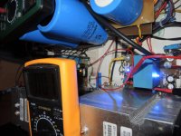
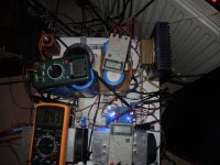
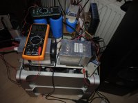
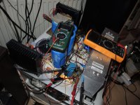
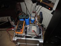
Real Time 6 Hours Sound and Stable Test
OK here we go.
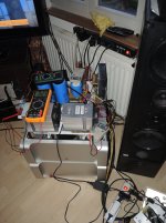
A small foreword:
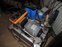
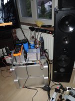
Left Channel (Green & Yellow Digital Meter) as well as the PSU with the 60'000UF Capacitor is the Transistorized Amplifier.
Running on 35 Volts RE=10 Ohm, should be 8 to get full power.
Right Channel ( grey digital Meters) as well as the smaller 22'000UF Capacitors is the IC Class A at least the Output is class a.
Running on 37Volts with RE=15 Ohm, 10 Ohm is too much and pull gain of the OP down. Still get a 12.5 @8 Ohm Watts out of it.
My Speakers have a Resistance of 4.7 Ohm
Brand is I.Q Series 4 Manufactured in 1992. Three Way from Germany, Drivers are VIFA.
Preamp: is Audio Research SP9 build 1978 using Tubes 6DJ8 would be the original but using Telefunken ECC88
Source: Digital Radio
Turntables:
Revox B795 Linear Tracking
Revox B790 Varyspeed Linear Tracking
Cartridge: Ortofon 2MBlack & Ortofon Turbo 3 MC
Second Turntable:
Project VT-E: Standing up
Cartridge: Ortofon OM 5E
Philips CD Player:
Bit Stream 850 One bit
The Sound:
Sound is wide open clear
Bass, is smooth powerful
Mid-range is Wide Broad
High; Fine with lots of timbre, sweet full of swing not hurting the ears..
Sound Stage is good gives a good positioning of the Instruments(while playing Live Music)
This is the Start of 4 day Stress Test for the Amplifier.All zou read here is after about 6 hours Time running and I will make it 12 hours and then taking pics again..so it will be 3 am when I come to bed.. then tomorrow evening making adjustment on what I think is not good.. Saturday Sunday the amps are in for 24 hours Stress test.
Since I use two different builds, with the same (Almost) input impedance and Gain, to verify which of both makes better sound and sense to build. ( I will build both anyway,, Just got another package with Parts..
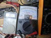
Ampere at start 6 and a half hour ago was for the Transistor 3.55 Amp and for the IC it was 3.65 amp. It should be visa versa.
DC output on that Transistor Amp which is from input to output CLASS A. has to be revised one more time and I think PID adjusted in the circuit
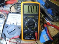
DC Output on the IC amp .. very good, stays withing 10mv as long as the amp isn't driven into clipping and also then it goes up tp a max of 100mv
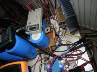
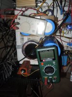
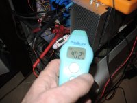
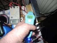
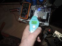
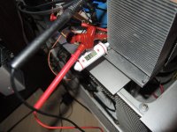
For the heat is the same. Take a look where I measure the heat of the Sink it read 40 degrees C but at a lower point you can see that the stationary Temp meter is reading 53C. this is the effectiveness of Active Cooling.
Ok. Each Pic is named for what it stands.
Inputs are welcome..
Next step is 24 hour real run with loudspeaker.
On that two hour run from this evening the heating of the transistors was relatively low 50C max 55C. the fan which makes the active cooling turns at 380RPM its rather noiseless.. The 200Watt Resistor get's about 90C screwed onto a Anodized HEAT SINK 15cm X 15cm by 5cm latter one is thickness..
Thanks for Reading..
OK here we go.
A small foreword:
Left Channel (Green & Yellow Digital Meter) as well as the PSU with the 60'000UF Capacitor is the Transistorized Amplifier.
Running on 35 Volts RE=10 Ohm, should be 8 to get full power.
Right Channel ( grey digital Meters) as well as the smaller 22'000UF Capacitors is the IC Class A at least the Output is class a.
Running on 37Volts with RE=15 Ohm, 10 Ohm is too much and pull gain of the OP down. Still get a 12.5 @8 Ohm Watts out of it.
My Speakers have a Resistance of 4.7 Ohm
Brand is I.Q Series 4 Manufactured in 1992. Three Way from Germany, Drivers are VIFA.
Preamp: is Audio Research SP9 build 1978 using Tubes 6DJ8 would be the original but using Telefunken ECC88
Source: Digital Radio
Turntables:
Revox B795 Linear Tracking
Revox B790 Varyspeed Linear Tracking
Cartridge: Ortofon 2MBlack & Ortofon Turbo 3 MC
Second Turntable:
Project VT-E: Standing up
Cartridge: Ortofon OM 5E
Philips CD Player:
Bit Stream 850 One bit
The Sound:
Sound is wide open clear
Bass, is smooth powerful
Mid-range is Wide Broad
High; Fine with lots of timbre, sweet full of swing not hurting the ears..
Sound Stage is good gives a good positioning of the Instruments(while playing Live Music)
This is the Start of 4 day Stress Test for the Amplifier.All zou read here is after about 6 hours Time running and I will make it 12 hours and then taking pics again..so it will be 3 am when I come to bed.. then tomorrow evening making adjustment on what I think is not good.. Saturday Sunday the amps are in for 24 hours Stress test.
Since I use two different builds, with the same (Almost) input impedance and Gain, to verify which of both makes better sound and sense to build. ( I will build both anyway,, Just got another package with Parts..
Ampere at start 6 and a half hour ago was for the Transistor 3.55 Amp and for the IC it was 3.65 amp. It should be visa versa.
DC output on that Transistor Amp which is from input to output CLASS A. has to be revised one more time and I think PID adjusted in the circuit
DC Output on the IC amp .. very good, stays withing 10mv as long as the amp isn't driven into clipping and also then it goes up tp a max of 100mv
For the heat is the same. Take a look where I measure the heat of the Sink it read 40 degrees C but at a lower point you can see that the stationary Temp meter is reading 53C. this is the effectiveness of Active Cooling.
Ok. Each Pic is named for what it stands.
Inputs are welcome..
Attachments
-
 7. Test Setup Class A_s.jpg209.4 KB · Views: 83
 -
 8. Test Setup_.jpg327.3 KB · Views: 75
 -
 9. Class A under Sound Test-side view_s.jpg191.6 KB · Views: 60
 -
 10. Top View with Measurements AMPERE - DC OUT_s.jpg184 KB · Views: 76
 -
 6. PSU Rigth Channel_s.jpg213.8 KB · Views: 73
 -
 5. Class A in Action front view_s.jpg154.9 KB · Views: 69
 -
 4. Class A in side view Left Channel_s.jpg227.3 KB · Views: 77
 -
 3. Power Drop of PSU left Channel_s.jpg308.9 KB · Views: 90
 -
 2. Class A Contuinity Test_s.jpg341.9 KB · Views: 118
 -
 1.Class A Sound & Dynamic Test_s.jpg188.2 KB · Views: 116
Last edited:
Part two:
Thanks for Reading
Thanks for Reading
Attachments
-
 14. Heat Dissipation of Active Cooling After 6 Hours_s.jpg142.2 KB · Views: 93
 -
 13. Resistor Temp Measurement after 6 Hour Run_s.jpg115.2 KB · Views: 87
 -
 12. Second channel - IC - Resistor Heat Test After 6 Hours_s.jpg138.6 KB · Views: 106
 -
 11. Surrounding Air Temp Measurement after 6 hours_s.jpg146.3 KB · Views: 106
 -
 15. Class A Temp Test after 6 Hours of Run_s.jpg199.9 KB · Views: 105
Hi Mark
yes I do know that. That's why I usually point the themometer onto that sticker on top of the heatsinks..
And as you see just to make sure that I get correct measurment, I use these white Thermometer which are sticked between the aluminum sinks.. these are very correct.. in picture 3 you will see that blueish shine from measuring on that resistor.. for me its important, not only to know the exact heat of the piece measured but also always on the same spot.
BTW the new Board for the Transistor Version is finished, meaning made the PCB, but not drilled yet.. Tomorrow I will put it together..
Changed a few things, like using 42Volts +- using 7.5 Ohm RE this is a BIAS of 5.6Amps
But it still drops to to 5.4 amp after 1 hour and as I see now after 15 hours of using it to 5.14 Amps with 39 instead of 44 Volts.. The first 2.- 4 hours Voltage will be at 42. Now its a mere 39.8volts with 65Degrees Celsius on the sink..
So I will need to have to order new Transformers, 750VAC instead of the one 500VAC I use now..
So I get max output at up to 75k 14.2 volts RMS into 8 Ohms that's a mere 25Watts.If I choose bandwith up to 100Khz then I have to sacrifice to - 3 db But this is because of the Ringing in BD139 and in the input Trasnsistor which is BC556. But after about 2 hours output is dropping down to 13.8Volts until the amp clips.. and it clips simultaneously on both side of the Waveform.
Sound is very good..
I also own some Pass Amps and so I have the chance to compare..Also have access to Rowen, and other good Amps to compare.. Friend of mine got a Krell. Macintosh and more.. no problems there..
BTW I am very pleased and thankfull that you guys help me to get that Amp done.
Now the Amp is running continued for 16 hours.. without any failure or hickups.. the heat stays at around 65 / 68 C.. Acceptable.
Right Now I' designing an Air Channel so I need only max 2 low turning Fans to keep the heat at max 75C when the amp is in the Box.
Of course I will make the Cirquit available as soon I'm satisfied with everything..
Also Layout of the PCB as well all Measurements as soon its finish, hopefully in two weeks from now. There is still a lot of work to be done..
I had to redesign the Layout of the PCB, cause I forgot the input line and a small powerline when I made Changes to version two.. Now version 3 has all of it.. also some distances, needet adjustment, because components where touching each other..
OK its half past midnight it's time to take a rest..the Amp will run for itself until tomorrow morning 8 am.
Thank you for your input it's really appreciated
Regards Chris
Last edited:
- Home
- Design & Build
- Construction Tips
- Building a Class Amplifier from Scratch