Assembling the board - Output Transistors and Pressure Plate
Hi Guys
I'm pretty sure that most of you know how to assemble a PCB..
Usually starting from the small units or components to the bigger and then to the large ones.
This also counts for my design of the Amplifier we are talking about.
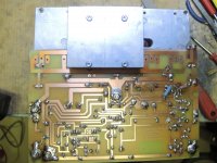
But this amp is a bit difficult, since I use a Active Heat-sink. And some of the components are covered by the Heat-sink.
This makes it necessary to build that amp in three step, meaning assembling the PCB
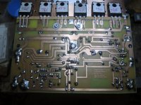
When all Resistors and fuse sockets, PID (IC SOCKETS) have been soldered then the next step must be that we insert these two 12000uf 63Volts Caps and solder these to the board.
After that we either solder or just plug in the Input Transistor. As the PCB I use is laid out with a Socket for the Transistor and it's Noise killer small (usually about 50pf) Capacitors, plug in that socket with the transistor already soldered to it.
But first we connect the DC lines +- and GND to the board and confirm the Voltages. Hooking up a AMP Meter to + Fuse.
Check that both RAIL VOLTAGES are correct reading according to the Transformers used.
When this is OK check the PID Socket Pin No. 7 for + Voltage according to used Regulator and also check the PID Socket Pin No 4 for - or negative Voltage according to used Regulator.
When all this fits, switch of the PSU take a 2 - 10 Ohm resistor and shunt the VDC+ and VDC- to GND, so you can't measure more than may a few volts not exceeding 2Volts.
Now if this has been done successful then insert the Input transistor but do not apply power yet. Turn VR1 full to left and then to the middle.
If you use a multi turn VR then turn full left first and then 12.5 turn to the right.this would be about the middle for a 25 turn VR.
Hock up your Signal Generator set the frequency to 1khz SINE WAVE and then switch on your Oscilloscope, set it AC Input to 5 Volts division, never mind what channel you use. Now hook up the Oscilloscope Probe on the Collector of the Input Transistor.
Switch on the the power of the PCB and check the Sine wave displayed on the screen of the Oscilloscope. Now increase the signal from the Signal Generator until the Sine wave clips on either side. Decrease the Signal just a little bit that you have identical + and - curves of both the positive and negative parts on the sine wave.
Increase again until one side clips and then increase that there is a REAL CLIP. Now turn the VR 1.
For Positive CLIP in Clockwise Direction and for NEGATIVE CLIP turn Counter Clockwise until both of the WAVE FORMS ARE IDENTICAL without clip. if you turned up your Signal Generator to far, so that both of Positive and Negative Curve clips, just turn down a little bit until on Curve is not clipping anymore and then adjust the VR once more.
If you have done this then there is no further adjustment needed once the AMP has been assembled with all components. And output will be very close to 0Volts DC - if you use PID then it will be just about 5 Millivolts and it is not forbidden to correct that, using either PIC ADJUSTER or VR1. But this time turn very gently and slow so the DMM reads 0.000 Volts or not more than .5Millivolts. But this after the amp has been completed.
As a next insert the Drive Transistors and then Check for Solder shorts etc.!
Usually when I have finished the assembly of a PCB I will clean the PCB with Alcohol based fluids like Isopropanol. Thus cleaning good and drys fast.
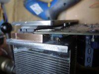
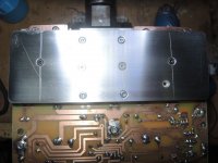
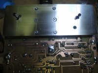
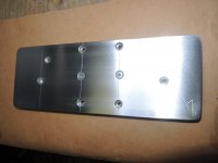
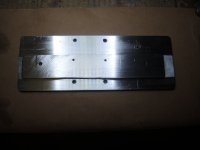
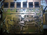
Then Soldering the OUTPUT TRANSISTORS in place, screwing them down or using a Pressure Plate, use a Torque Wrench to fasten all the relevant Bolts with the same Torque. Of course add some HEAT TRANSFER COMPOUND, Like UNICK HEATSINK COMPOUND, to the Transistors. If possible do not use Rubber thermal Pads, as these can't cope with the heat Generated in a CLASS A Amplifier.
The Pressure Plate you see in the Picture is a Prototype made by hand, with just a Saw, a File a Drill and sandpaper..
There is much more we can do while building our amps. I just noted down, from my sight the most important tasks.
The following Pics are just made to have it explained with Pics, so that the way can be seen and it's only for Assembling Output Transistors. If anyone needs the full concept just ask, I will place it here.
This Assembly hasn't been done yet, this is only to show, how it could look like.
This PCB will exchange the PCB which are already seen in the last Picture of the Amplifier.. Soon.
Any Question, or advices are as always welcome.
Thanks for Reading.
Chris Hess
Hi Guys
I'm pretty sure that most of you know how to assemble a PCB..
Usually starting from the small units or components to the bigger and then to the large ones.
This also counts for my design of the Amplifier we are talking about.
But this amp is a bit difficult, since I use a Active Heat-sink. And some of the components are covered by the Heat-sink.
This makes it necessary to build that amp in three step, meaning assembling the PCB
When all Resistors and fuse sockets, PID (IC SOCKETS) have been soldered then the next step must be that we insert these two 12000uf 63Volts Caps and solder these to the board.
After that we either solder or just plug in the Input Transistor. As the PCB I use is laid out with a Socket for the Transistor and it's Noise killer small (usually about 50pf) Capacitors, plug in that socket with the transistor already soldered to it.
But first we connect the DC lines +- and GND to the board and confirm the Voltages. Hooking up a AMP Meter to + Fuse.
Check that both RAIL VOLTAGES are correct reading according to the Transformers used.
When this is OK check the PID Socket Pin No. 7 for + Voltage according to used Regulator and also check the PID Socket Pin No 4 for - or negative Voltage according to used Regulator.
When all this fits, switch of the PSU take a 2 - 10 Ohm resistor and shunt the VDC+ and VDC- to GND, so you can't measure more than may a few volts not exceeding 2Volts.
Now if this has been done successful then insert the Input transistor but do not apply power yet. Turn VR1 full to left and then to the middle.
If you use a multi turn VR then turn full left first and then 12.5 turn to the right.this would be about the middle for a 25 turn VR.
Hock up your Signal Generator set the frequency to 1khz SINE WAVE and then switch on your Oscilloscope, set it AC Input to 5 Volts division, never mind what channel you use. Now hook up the Oscilloscope Probe on the Collector of the Input Transistor.
Switch on the the power of the PCB and check the Sine wave displayed on the screen of the Oscilloscope. Now increase the signal from the Signal Generator until the Sine wave clips on either side. Decrease the Signal just a little bit that you have identical + and - curves of both the positive and negative parts on the sine wave.
Increase again until one side clips and then increase that there is a REAL CLIP. Now turn the VR 1.
For Positive CLIP in Clockwise Direction and for NEGATIVE CLIP turn Counter Clockwise until both of the WAVE FORMS ARE IDENTICAL without clip. if you turned up your Signal Generator to far, so that both of Positive and Negative Curve clips, just turn down a little bit until on Curve is not clipping anymore and then adjust the VR once more.
If you have done this then there is no further adjustment needed once the AMP has been assembled with all components. And output will be very close to 0Volts DC - if you use PID then it will be just about 5 Millivolts and it is not forbidden to correct that, using either PIC ADJUSTER or VR1. But this time turn very gently and slow so the DMM reads 0.000 Volts or not more than .5Millivolts. But this after the amp has been completed.
As a next insert the Drive Transistors and then Check for Solder shorts etc.!
Usually when I have finished the assembly of a PCB I will clean the PCB with Alcohol based fluids like Isopropanol. Thus cleaning good and drys fast.
Then Soldering the OUTPUT TRANSISTORS in place, screwing them down or using a Pressure Plate, use a Torque Wrench to fasten all the relevant Bolts with the same Torque. Of course add some HEAT TRANSFER COMPOUND, Like UNICK HEATSINK COMPOUND, to the Transistors. If possible do not use Rubber thermal Pads, as these can't cope with the heat Generated in a CLASS A Amplifier.
The Pressure Plate you see in the Picture is a Prototype made by hand, with just a Saw, a File a Drill and sandpaper..
There is much more we can do while building our amps. I just noted down, from my sight the most important tasks.
The following Pics are just made to have it explained with Pics, so that the way can be seen and it's only for Assembling Output Transistors. If anyone needs the full concept just ask, I will place it here.
This Assembly hasn't been done yet, this is only to show, how it could look like.
This PCB will exchange the PCB which are already seen in the last Picture of the Amplifier.. Soon.
Any Question, or advices are as always welcome.
Thanks for Reading.
Chris Hess
Attachments
-
 1. Taking Measurements.jpg209.8 KB · Views: 239
 -
 10. Class A Single End - Running.jpg202.4 KB · Views: 94
 -
 9. Final Check Before Clean and Assembling.jpg186.9 KB · Views: 79
 -
 8. Check Stands for Full Pressure.jpg125.4 KB · Views: 68
 -
 7. Check Free Space - Before Assemling.jpg141.3 KB · Views: 74
 -
 6. Screwing down Pressureplate - Check for Bending.jpg191.9 KB · Views: 82
 -
 5. Placing Pressure Plate.jpg183.2 KB · Views: 230
 -
 4.Taking Place of Transistors - Ready to Solder.jpg216.7 KB · Views: 256
 -
 3. Pressure Plate Output Transistors Bottom side.jpg136.5 KB · Views: 232
 -
 2. Pressure Plate Output Transistors.jpg117.4 KB · Views: 235
Last edited:
Finalized the 6 Transistor Version.
Guys
So, finally the 6 transistor version has been completed.
Please check this link from my other Thread for the Specs.
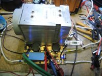
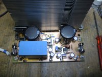
so the pics just showing the assembling of the Power transistors to the PCB and then to Heat Sink
Bolts Torque is 1.5nm, there are 6 Bolts @3mm Diameter used to keep pressure on the Transistors evenly. That's why that Torque note..
The Rest is self understandable..
Any Question just ask, and this is not finish, it's just the prototype,
The follow up will have a new BOARD because of change of the Heat dissipating copper Plate, so that board here will not fit..
And also Pressure Plate as well as the 10mm thick Copper Heat dissipating plate are made with CNC and this time these look just Beautiful even no one will ever see but me. But, this is my way to do things.
Gents thanks for reading, here a few Pics..
Regards
Chris Hess
Guys
So, finally the 6 transistor version has been completed.
Please check this link from my other Thread for the Specs.
so the pics just showing the assembling of the Power transistors to the PCB and then to Heat Sink
Bolts Torque is 1.5nm, there are 6 Bolts @3mm Diameter used to keep pressure on the Transistors evenly. That's why that Torque note..
The Rest is self understandable..
Any Question just ask, and this is not finish, it's just the prototype,
The follow up will have a new BOARD because of change of the Heat dissipating copper Plate, so that board here will not fit..
And also Pressure Plate as well as the 10mm thick Copper Heat dissipating plate are made with CNC and this time these look just Beautiful even no one will ever see but me. But, this is my way to do things.
Gents thanks for reading, here a few Pics..
Regards
Chris Hess
Attachments
-
 9. Raila & Current.jpg330.5 KB · Views: 62
 -
 9. Applying Power and Sound input & Loudspeaker.jpg236.4 KB · Views: 105
 -
 8. Checking The PCB for Shorts.jpg231.6 KB · Views: 54
 -
 7. Screw down the Drive Transistors.jpg112.6 KB · Views: 63
 -
 6. Check - Transistor Sandwitch-.jpg194 KB · Views: 48
 -
 5. Set Pressure Plate and Screw it down..jpg152.5 KB · Views: 66
 -
 4. Applying Unick Heat Transfer Compound to Drive Transitors.jpg129.1 KB · Views: 61
 -
 3. Applying Unick Heat Transfer Compound to Transistors.jpg205.9 KB · Views: 62
 -
 2. Appliying Unick Heat Transfer Compound and Mica 0.005mm thick.jpg139 KB · Views: 65
 -
 1. Soldering Power Transistors.jpg207.9 KB · Views: 87
Active Heat Sink Extensions Made with CNC
Hi Guys
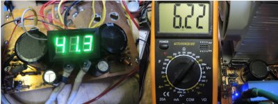
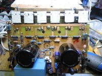
As you can see in my last post, there is the 6 Output Transistor Version of that Single End Class A Amplifier which I build, and the reason to do so, is that I can give more Voltage and also more Idle current to that circuit which is at present time About 5.6 Ampere @ 42volts * its 41.5 * should be 42.
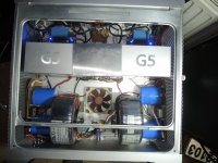
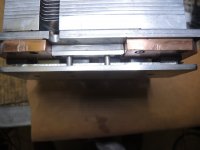
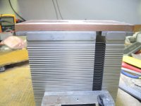
Now todo so I needed to extend the Copper of the Active Heatsink which I took out of a POWER MAC or MAC PRO, whatever you like, and made that extension by hand to test.
Now it's testing already for one month, everyday at least 5 - 8 Hours run-time.
The Amp sounds great has everything what one can expect from a class a. distortion is as low as .1 over the full Power Band.. I can live with that. There fore I bought a HP distortion Analyzer because a very smart man told me, that this is the only way to check distortion. And he was right. Oh I bought two of these Analyzers, the second one was Broken when I got it, but have fixed it already and now both of them working like a dream.
I add a few pictures which in fact are self explainable how to extend the Copper part of a MAC PRO HEAT SINK the professional way. But it's really expensive to do so at least here in Swiss. Cost me a fortune, other people buying a complete Amp Case inclusive heat sink for that price.. But I can build now 3 Stereo Amps with that. Even I want do that.
The next one is going to one without FAN. Exactly same Circuit.
OK. here the pictures, and to make it more understandable, Pic 4 is the Amp already build with 2 Transistors. and it's running just smooth as well as the 6 transistor version you could see in my prior post.
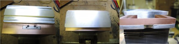
The Plates have been made Professional by a Milling Company using CNC according to my Measures.
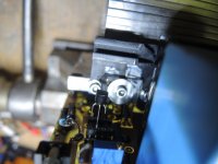
Pic 1. is showing an Original ACTIVE MAC PRO Heat Sink which was the Motorola Version.
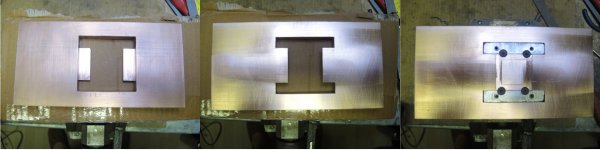
Pic 1.2.3 is a close up to show the "Working Traces, as with this heat sink only one transistor can be placed I had to extend that for my TWO Output Transistor Version.
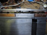
Pic 1.3.3, is the finished extension made by HAND.
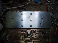
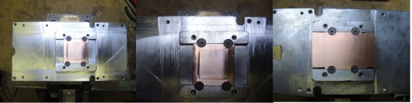
Pic 2, is the CNC COPPER PLATE made by that Mechanical Milling Company..I need to forget the costs..It was just extremely high. They take the money from the living ones..
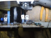
Pic 4. is the 6 transistor Version Running on a 2 Transistor Active Heat Sink.. with only 2 Transistors mounted.
Pic 5. is the New Pressure Plate also made by the same company who made the copper plate,, I had them make 6 Pressure Plates.,.1 Cost inclusive Material about 50Swiss Francs.. that's 52US$.!
Pic 6 HP distortion analyzer Model 331A. Not the newest but it does it's Duty. and it measures quite good. and we can take a look at the Second Harmonic as well while measuring distortion.
Thanks for Reading,
Chris Hess
Hi Guys
As you can see in my last post, there is the 6 Output Transistor Version of that Single End Class A Amplifier which I build, and the reason to do so, is that I can give more Voltage and also more Idle current to that circuit which is at present time About 5.6 Ampere @ 42volts * its 41.5 * should be 42.
Now todo so I needed to extend the Copper of the Active Heatsink which I took out of a POWER MAC or MAC PRO, whatever you like, and made that extension by hand to test.
Now it's testing already for one month, everyday at least 5 - 8 Hours run-time.
The Amp sounds great has everything what one can expect from a class a. distortion is as low as .1 over the full Power Band.. I can live with that. There fore I bought a HP distortion Analyzer because a very smart man told me, that this is the only way to check distortion. And he was right. Oh I bought two of these Analyzers, the second one was Broken when I got it, but have fixed it already and now both of them working like a dream.
I add a few pictures which in fact are self explainable how to extend the Copper part of a MAC PRO HEAT SINK the professional way. But it's really expensive to do so at least here in Swiss. Cost me a fortune, other people buying a complete Amp Case inclusive heat sink for that price.. But I can build now 3 Stereo Amps with that. Even I want do that.
The next one is going to one without FAN. Exactly same Circuit.
OK. here the pictures, and to make it more understandable, Pic 4 is the Amp already build with 2 Transistors. and it's running just smooth as well as the 6 transistor version you could see in my prior post.
The Plates have been made Professional by a Milling Company using CNC according to my Measures.
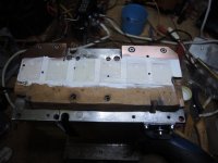
Pic 1. is showing an Original ACTIVE MAC PRO Heat Sink which was the Motorola Version.
Pic 1.2.3 is a close up to show the "Working Traces, as with this heat sink only one transistor can be placed I had to extend that for my TWO Output Transistor Version.
Pic 1.3.3, is the finished extension made by HAND.
Pic 2, is the CNC COPPER PLATE made by that Mechanical Milling Company..I need to forget the costs..It was just extremely high. They take the money from the living ones..
Pic 4. is the 6 transistor Version Running on a 2 Transistor Active Heat Sink.. with only 2 Transistors mounted.
Pic 5. is the New Pressure Plate also made by the same company who made the copper plate,, I had them make 6 Pressure Plates.,.1 Cost inclusive Material about 50Swiss Francs.. that's 52US$.!
Pic 6 HP distortion analyzer Model 331A. Not the newest but it does it's Duty. and it measures quite good. and we can take a look at the Second Harmonic as well while measuring distortion.
Thanks for Reading,
Chris Hess
Attachments
-
 5. New Pressure Plate for 6 Transistor Versin Tested..jpg374.7 KB · Views: 82
 -
 4. 2 Transistor Version Active Heat Sink.jpg205.9 KB · Views: 87
 -
 3. Sideview Mounted Copper Plates with Active Heatsink.jpg182.5 KB · Views: 88
 -
 2. New CNC Produced COpper Extension Plate Version 6 Transistors.jpg411 KB · Views: 87
 -
 1. Extending 1 Transitor Heatsink to 1 Transistors.jpg544.2 KB · Views: 76
 -
 6.Distortion Analyzer.jpg201.9 KB · Views: 67
Last edited:
Finally the Project has been finished successfully
Hi everybody,
The 6 parallel Output Transistor Version has replaced the 2 parallel transistor Version in that BOX.
Now following off boards Components failed afterwards.
1. 24Volts Regulator for the Softstart Circuit of the Amplifier - Regulator Burned even it was secured with Voltage Drop Resistor which is connected in Series with the RELAIS of the softstart. Unbelievable but can't help it..
2. Even worse the MAIN FUSE SOCKET at the BACK of the 220 - 230 Volts Line burned inside the SOCKET. But fuse 3.15Amps, didn't blow. And the way it burned is "Strange" because it burned inside the SOCKET where the OUTPUT of the wire which goes to Switch and Transformer is connected to..
So I think there it is necessary to make a small PCB for a RELAIS which will switch the load (The Amps) instead passing it through the switch.
Everything else is a DREAM, Sound is sweet powerfull with Punch where it is requested to have punch, soft where one can expect to be soft, clear definitions of the STAGE and the instruments involved. Absolutely clean highs in the above 10k level. I have recently tested myself for hearing abilities - its 13.4 k - 20 db to other sounds at 10khz. Even I have to fight with Tinnitus @12.5k wich disturbs me on both ears a great deal of the daily time. Very Broad Midrange and deep and clean BASS down to subsonic. Wide soundstage.
I'm satisfied with it..
Had some friends and strangers listen to it, and all of them in the ability to hear up to 16khz.. they were fascinated about the sound reproduction of this amp.
Thanks for reading
Respect to you all
Chris Hess
If there are typos and likewise then I beg your pardon. Spellchecker don't function on this iMAC or better say Windows 10LTSB..
Last edited:
Update on the Class A
So. it's time to write about the shadow sides of DIY High Current Class A Power Amps.
As you can read in my last Post, some add on Parts just stopped to work of Blew up with some noise, and this since I exchanged both amps in that BOX.
However, I suspected something like that, and last night again the DESTROYER OF ELECTRONICS COMPONENTS visited my CLASS A Single End.
This time it removed/blew up a 25A/400Volts Bridge Rectifier with a big BANG and also some Indian Smoke Signals. And this at midnight.!!
This has happen after I pushed the wrong button on my remote Control to Start/Stop the Amplifier (This cutting main Power).
After I recognized that the AMP had been switched off accidentally by pushing the wrong button, I pushed the Start Button once but the amp wouldn't switch on. OK, I thought the Amp has run for almost 12 hours without switching off, it might need a second try.
So I pressed that start button on my remote controller again, and yea the AMP started up, the next I knew a BIG BANG (Midnight) and all I could hear on the left channel was a 50 Hertz HUM. The right channel performed normally. Switched off the AMP, then removed the Plus of the Speaker Cable (this AMP DOES NOT USE a SPEAKER PROTECTION other than the FUSES) and switched it on again. The first Check showed me that the AMPLIFIER was in working Condition, as both LED to show if FUSES are blown, lit up.
And about 5 seconds later again a BANG, and smoke out of the left side PSU..
Took a glimpse at the Rectifier Bridge, and could see a nice hole there right beside the MINUS binding point of the rectifier bridge.
OK, I thought at least, the AMP hasn't broke down. But unbelievable, this PSU has run with the 2 Transistor version for 8 Months..
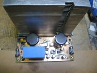
With no failure and never showed anything the it would blow up, but not even 2 weeks since I exchanged the boards for that 6 Transistor Version had two fails of add on components already and now this with that PSU.. So I need to recalculate the PSU. This morning removed the side cover De-soldered that Bridge Rectifier and Exchanged it with a FAGOR 25Amps / 800Volts. Started up the amp and everything was good again. Sound nice as ever, checked output DC = 0.0000VDC
Then I took a good look at the old Rectifier and to my surprise had to find out that this one wasn't 25A/ 400 but rather 15A/200V only. So I forgt to change that when I changed the 6 Transistor board.
As the 6Transistor version pulls about 1 Ampere more Idle Current, than the two Transistor version, its understandable that this Bridge blew up..
Because the Rectifier Bridges are not mounted on a heat sink cooled by surrounding air only..
But this I will change the coming days, or use a Heat Sensor to cut of power when overheated. I personally think that mounting a heat sink on top of the Rectifier Bridges, is the better way to go.
The other side of the AMP, meaning the second PSU had already the 25A/800Volts soldered in.. So. it's my BAD
But worst never comes alone. It destroyed also my Power Switch.. once more.
So, NOW it's time to create a Relays driven power Switch.
So, everything has it's good and also bad sides, and therefore if we go high power high current, only top Grade Components should be used, it showed this another time to me.
Thanks for reading
Chris Hess
So. it's time to write about the shadow sides of DIY High Current Class A Power Amps.
As you can read in my last Post, some add on Parts just stopped to work of Blew up with some noise, and this since I exchanged both amps in that BOX.
However, I suspected something like that, and last night again the DESTROYER OF ELECTRONICS COMPONENTS visited my CLASS A Single End.
This time it removed/blew up a 25A/400Volts Bridge Rectifier with a big BANG and also some Indian Smoke Signals. And this at midnight.!!
This has happen after I pushed the wrong button on my remote Control to Start/Stop the Amplifier (This cutting main Power).
After I recognized that the AMP had been switched off accidentally by pushing the wrong button, I pushed the Start Button once but the amp wouldn't switch on. OK, I thought the Amp has run for almost 12 hours without switching off, it might need a second try.
So I pressed that start button on my remote controller again, and yea the AMP started up, the next I knew a BIG BANG (Midnight) and all I could hear on the left channel was a 50 Hertz HUM. The right channel performed normally. Switched off the AMP, then removed the Plus of the Speaker Cable (this AMP DOES NOT USE a SPEAKER PROTECTION other than the FUSES) and switched it on again. The first Check showed me that the AMPLIFIER was in working Condition, as both LED to show if FUSES are blown, lit up.
And about 5 seconds later again a BANG, and smoke out of the left side PSU..
Took a glimpse at the Rectifier Bridge, and could see a nice hole there right beside the MINUS binding point of the rectifier bridge.
OK, I thought at least, the AMP hasn't broke down. But unbelievable, this PSU has run with the 2 Transistor version for 8 Months..
With no failure and never showed anything the it would blow up, but not even 2 weeks since I exchanged the boards for that 6 Transistor Version had two fails of add on components already and now this with that PSU.. So I need to recalculate the PSU. This morning removed the side cover De-soldered that Bridge Rectifier and Exchanged it with a FAGOR 25Amps / 800Volts. Started up the amp and everything was good again. Sound nice as ever, checked output DC = 0.0000VDC
Then I took a good look at the old Rectifier and to my surprise had to find out that this one wasn't 25A/ 400 but rather 15A/200V only. So I forgt to change that when I changed the 6 Transistor board.
As the 6Transistor version pulls about 1 Ampere more Idle Current, than the two Transistor version, its understandable that this Bridge blew up..
Because the Rectifier Bridges are not mounted on a heat sink cooled by surrounding air only..
But this I will change the coming days, or use a Heat Sensor to cut of power when overheated. I personally think that mounting a heat sink on top of the Rectifier Bridges, is the better way to go.
The other side of the AMP, meaning the second PSU had already the 25A/800Volts soldered in.. So. it's my BAD
But worst never comes alone. It destroyed also my Power Switch.. once more.
So, NOW it's time to create a Relays driven power Switch.
So, everything has it's good and also bad sides, and therefore if we go high power high current, only top Grade Components should be used, it showed this another time to me.
Thanks for reading
Chris Hess
Last edited:
The Follow up of Class A single End Amp
Gents
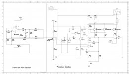
It's Saturday March 20th early afternoon and I just finished the new and further Circuit Diagram for you guys to SPICE the next Version of my CLASS A SINGLE END, Amplifier, with a somewhat other approach in the front end stage, and also with PID SERVO Regulation drawn as well.
I have to say, I have tested this amp in real already, and going to draw the ARTWORK, meaning, Layout PCB for two instances.
1: Active Heat-sink with FAN and a 6Paralleled Output Transistor Version
2: Passive Heat-sink without FAN and 10 Paralleled Output Transistor Version, Heat sink Size will be 400mm x 200 mm x 15 mm per side..
The Circuit I place is rather to TEST And SPICE than to build right away, as there are a few Features, which are not drawn in Circuit here, like Fine-tuning DC OUT at speaker Terminal. which can be tuned to be 0.00000 Volt.
Here the Circuit
Regards
Chris Hess
Gents
It's Saturday March 20th early afternoon and I just finished the new and further Circuit Diagram for you guys to SPICE the next Version of my CLASS A SINGLE END, Amplifier, with a somewhat other approach in the front end stage, and also with PID SERVO Regulation drawn as well.
I have to say, I have tested this amp in real already, and going to draw the ARTWORK, meaning, Layout PCB for two instances.
1: Active Heat-sink with FAN and a 6Paralleled Output Transistor Version
2: Passive Heat-sink without FAN and 10 Paralleled Output Transistor Version, Heat sink Size will be 400mm x 200 mm x 15 mm per side..
The Circuit I place is rather to TEST And SPICE than to build right away, as there are a few Features, which are not drawn in Circuit here, like Fine-tuning DC OUT at speaker Terminal. which can be tuned to be 0.00000 Volt.
Here the Circuit
Regards
Chris Hess
Attachments
REW Measurements CLASS A SINGLE END 1Watt 8Ohms
Gents,
Good morning from Switzerland on this very cold Sunday the March 21st.9:30 am.
I hope everyone is in good health, and enjoy a prosperous life.
The other Day, I have read here on this forum about REW,. This was quite sometime Back.
Then one Day while still in development Phase, of that class A, which I did not invent but Calculate and BUILD finally despite, many good meant advises to change to some other design, which I did not follow, because I had a dream and I wanted to become this dream true.
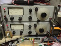
Now in the meantime, I bought a lot of equipment, like to Distortion analyzers, and also a TASCAM Sound interface to finally measure that Class A single end.
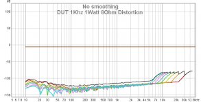
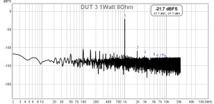
And here are the results, as it is not my way to falsify any results, So all measurement I made just an hour ago, are 1Watt @ 8ohms and already with this, the PEAK lamp of my sound interface Tascam US 1x2HR already lit up when connecting the output of the CLASS A to LINE INPUT with 1WATT.
Actually I don't mind if I fry that Brand New Tascam, but then I wouldn't be able to make accurate measurements and that's why I Set MAX INPUT of the TASCAM to 2.88Volts RMS which equals 1Watt, Passing a 100Watt Dummy load, and connection is made with a RCA direct connected to the DUMMY..
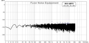
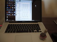
Here a few Pics of the measurement, starting out with the Equipment, Dummy Load, Computer used, and then Groundfloor Noise measure to know how much noise we have before I start to measure the AMP. But of course the AMPLIFIER measurements. As I can place only 10 Pictures I had to select the most important ones, so if any of you think, he or her wanted to take a look at this or another test, let me know..
Thanks for Reading.,
Chris Hess
Gents,
Good morning from Switzerland on this very cold Sunday the March 21st.9:30 am.
I hope everyone is in good health, and enjoy a prosperous life.
The other Day, I have read here on this forum about REW,. This was quite sometime Back.
Then one Day while still in development Phase, of that class A, which I did not invent but Calculate and BUILD finally despite, many good meant advises to change to some other design, which I did not follow, because I had a dream and I wanted to become this dream true.
Now in the meantime, I bought a lot of equipment, like to Distortion analyzers, and also a TASCAM Sound interface to finally measure that Class A single end.
And here are the results, as it is not my way to falsify any results, So all measurement I made just an hour ago, are 1Watt @ 8ohms and already with this, the PEAK lamp of my sound interface Tascam US 1x2HR already lit up when connecting the output of the CLASS A to LINE INPUT with 1WATT.
Actually I don't mind if I fry that Brand New Tascam, but then I wouldn't be able to make accurate measurements and that's why I Set MAX INPUT of the TASCAM to 2.88Volts RMS which equals 1Watt, Passing a 100Watt Dummy load, and connection is made with a RCA direct connected to the DUMMY..
Here a few Pics of the measurement, starting out with the Equipment, Dummy Load, Computer used, and then Groundfloor Noise measure to know how much noise we have before I start to measure the AMP. But of course the AMPLIFIER measurements. As I can place only 10 Pictures I had to select the most important ones, so if any of you think, he or her wanted to take a look at this or another test, let me know..
Thanks for Reading.,
Chris Hess
Attachments
-
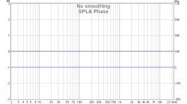 3.1 SPL& Phase.jpg64.8 KB · Views: 61
 -
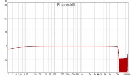 3.Phaseshift.jpg67.5 KB · Views: 61
 -
 4.DUT 1Khz 1Watt 8Ohm Distortion.jpg87.2 KB · Views: 56
 -
 2. DUT 3 1Watt 8Ohm & Distortion.jpg76.3 KB · Views: 55
 -
 1.FLoor Noise Equippment.jpg75.8 KB · Views: 51
 -
 MacbookPro.jpg153.2 KB · Views: 54
 -
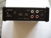 2. Tascam Back.jpg95.6 KB · Views: 53
 -
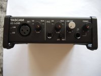 2. Tascam Front.jpg100 KB · Views: 58
 -
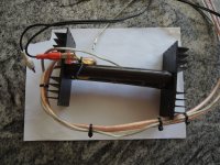 1.Dummy Load.jpg225.5 KB · Views: 69
 -
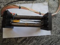 1.1.Dummy Load.jpg211.9 KB · Views: 93
Wrong Numbers - Sorry
Guys
PLEASE NOTE:
As I just had to find out there was a miscalculation of the Output Power which is what Mr. Nelson Pass told me, credit to the ones who own the credit..
So the actual output power which I was thinking is for 8 Ohms is actually 4 ohms when 8 Ohms speakers are connected..
Now, this means the OUTPUT Transistor drives 4 ohms half into the loudspeaker and half into the RE which is in fact "Current provider " for the amplifier.. this increases output power significantly to a higher level, but not for 8 Ohm, but 4 ohm instead..
Sorry for that misinformation.
Now I can not tell you the exact output Power @ 8Ohms because I need to get the load first, which in the end will reflect the true RMS POWER delivered into 8 Ohms.
Thanks @ Mr. Nelson Pass
I apologize that I did post wrong numbers.
I will place here the words of Mr. Pass
Quote:
As the big resistor goes down in value,
remember that it is parallel to the load, so 8 ohms bias resistor + 8 ohm loudspeaker
means that the transistor is driving 4 ohms."
End Quote
So other may not make this mistake as I did.
So the MAX OUTPUT POWER accidentally thought it would be @8 ohm is somewhere between 4 and 8 but the amplifier delivered 14.8VOLTS RMS into that..@0.1% distortion.. so please calculate by yourself, how much in fact is delivered to the speaker..
I always thought it is 27.179 Watt, but according this fact above, it is more,.
Sorry and Thanks for understanding. I just build amps because I love the challenge..
And I'm not here to cheat anyone with wrong numbers.
Regards Chris Hess
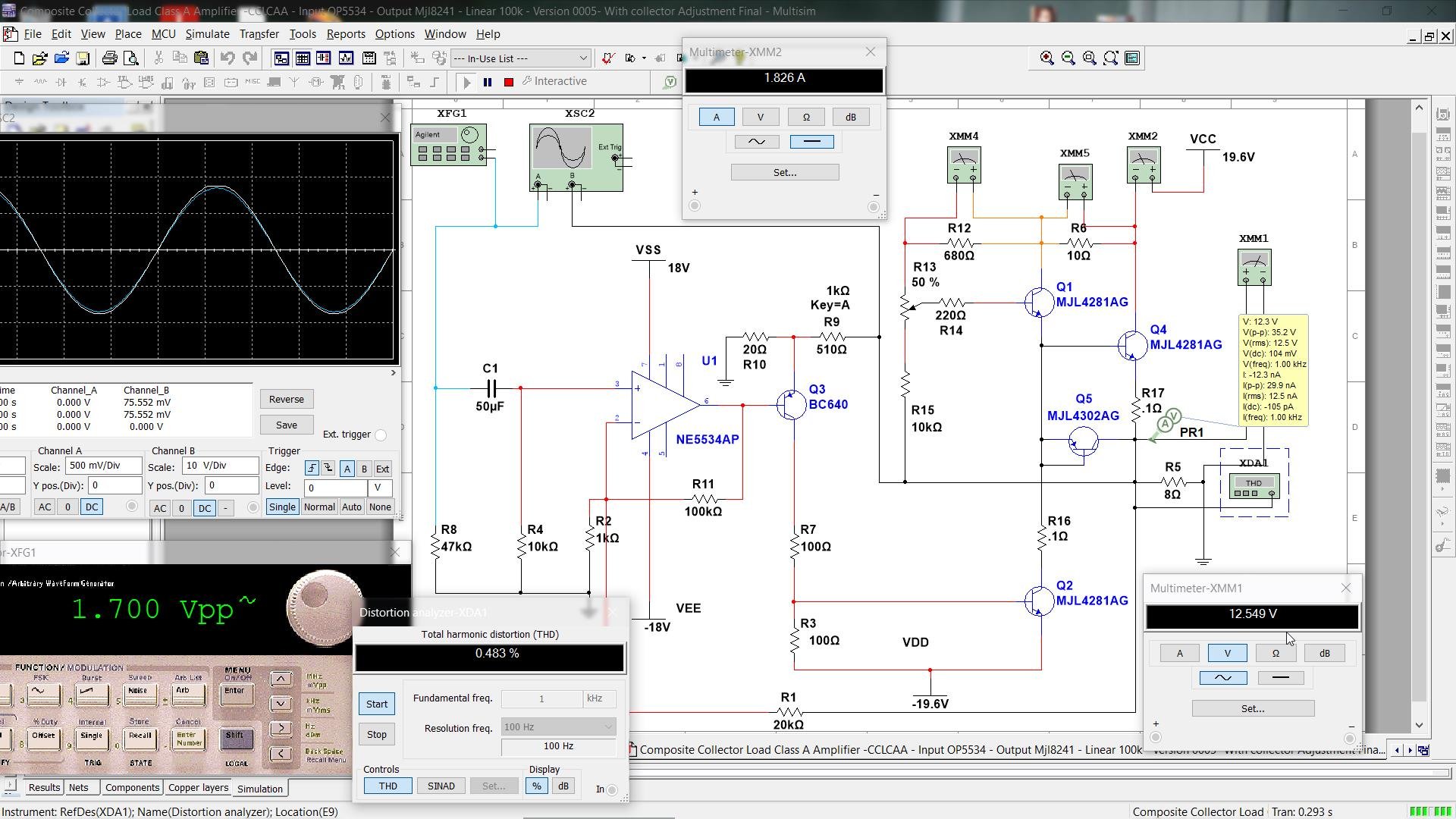
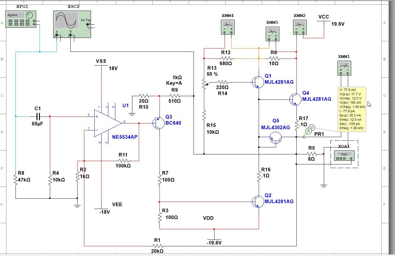
New Old Line, Class A - Compsoite Collector Load Class A
Guys,
That single end has been finished, I have been working on several Circuits and I would like to show some modificated Version of a Class A Amp which was introduced * according to this website here:
GB1527293A - Composite collector load for class a semiconductor amplifier
- Google Patents
* back in 1977.
I have build that one before, end of the eighties & beginning of the nineties, and made a modified version of a circuit I found in a Thai Electronic Magazine that time. This shows only the output stage as it was intended to use from the Owner of that Circuit.

I changed a few things when I build this in the nineties. This was actually a very good circuit as there are a few major points, which made it interesting.
I also use a PNP POWER TRANSISTOR instead of the High Speed Diode which passes Reverse Current from V- as using a transistor produces less Distortion. and give brings better bandwidth. In my Circuit underneath it's Q5.
1. Less Current for the more output power in True Class A
2. Less Heat because of less Idle Current
3. More Vout compared to rail voltage..
4. If used with Vrail +- 20 volts, output voltage @ 8 Ohms Load, 12Volts RMS is possible. with not more than 1.8 AMPS Idle Current
If used with 4 Ohms Load then output voltage of 10+ Volts RMS is possible with not more than 2.5 Amps Idle Current
And if used with 2 Ohms Load then still 9.5 Volts RMS are possible and this in TRUE CLASS A Mode. with about 4 Amps Current.
5. Idle Current can be half of a regular Class A and if will increase accoringly to Signal Strength. Up to the maximum which can be preset by a VR REF.
Negatively to say is that Distortion is rather high, it is very hard to have less than 0.01 % @1 Watt and it is normal to see about 0.5% at full level.
6. Bandwidth linearity is quite good and is within 0.2 DB from 10 - 100Khz, but this counts only for loads @ 8Ohms, when using 4 or 2 Ohm Loads bandwidth will be cut down to 70k respectively to 40 KHz for 4 and 2 Ohms.
7. Sound is fantastic as it is Pure and True Class A.
8. If used with 8 ohms Idle current can be set as low as 1.5 Ampere @Vrail +-20 volts, so 30 Watts is the passive heating of the amplifier..
9. Voltage can be increased without modification to Vrail +-24 Volts and so, also output power will increase.
10. Last but not least it's a low cost Amplifier which can be build with several Types of different output devices, like SC5200 and or MJL4281 which are a bit more expensive.
I add also my latest Schematic design with 4Paralell Output devices. Only to assure that the Subsonic Sounds also come across as real good sound..with puch and power.
I can not tell about the noise level, but as soon the PCB is made and tested I also will place this Data here. But it will take a while. The Test-version is free of noise & hum.
The 8 Ohm Load Version will not require to have COOLING FANS, but adequate heat sinks instead. The test version of this Amplifier is on my Work Bench, and I use two HP SMPS PSU from some old LAPTOP @18.5 Volts @6.5 Ampere to feed +- Rail Voltages.ohm Load
AMP has no hum and the one I test has a distortion under 0.05% @ 1 Watt 8
It claims up to 0.3% at full load which is Volts RMS or 32Volts Peak to Peak
which is about 16 Watts RMS.
May the one or other is interested to build it.. it's all really straight forward and not much problem to build.
The IC also can be adjusted for 0 volts output, * which in this circuit is not drawn* but can be achieved by placing a 100K VR between Pin 5 & Pin 8 and connecting center to Pin 7 via a 22kOhm Resistor. this way 0 volts down to 0.00000 can be adjusted using the VR.
It is advisable to use a linear VR 100K 25 turns. As soon I have drawn the PCB Layout I will place it here..
Guys, have fun.
Thanks for Reading..
Chris Hess
Guys,
That single end has been finished, I have been working on several Circuits and I would like to show some modificated Version of a Class A Amp which was introduced * according to this website here:
GB1527293A - Composite collector load for class a semiconductor amplifier
- Google Patents
* back in 1977.
I have build that one before, end of the eighties & beginning of the nineties, and made a modified version of a circuit I found in a Thai Electronic Magazine that time. This shows only the output stage as it was intended to use from the Owner of that Circuit.
I changed a few things when I build this in the nineties. This was actually a very good circuit as there are a few major points, which made it interesting.
I also use a PNP POWER TRANSISTOR instead of the High Speed Diode which passes Reverse Current from V- as using a transistor produces less Distortion. and give brings better bandwidth. In my Circuit underneath it's Q5.
1. Less Current for the more output power in True Class A
2. Less Heat because of less Idle Current
3. More Vout compared to rail voltage..
4. If used with Vrail +- 20 volts, output voltage @ 8 Ohms Load, 12Volts RMS is possible. with not more than 1.8 AMPS Idle Current
If used with 4 Ohms Load then output voltage of 10+ Volts RMS is possible with not more than 2.5 Amps Idle Current
And if used with 2 Ohms Load then still 9.5 Volts RMS are possible and this in TRUE CLASS A Mode. with about 4 Amps Current.
5. Idle Current can be half of a regular Class A and if will increase accoringly to Signal Strength. Up to the maximum which can be preset by a VR REF.
Negatively to say is that Distortion is rather high, it is very hard to have less than 0.01 % @1 Watt and it is normal to see about 0.5% at full level.
6. Bandwidth linearity is quite good and is within 0.2 DB from 10 - 100Khz, but this counts only for loads @ 8Ohms, when using 4 or 2 Ohm Loads bandwidth will be cut down to 70k respectively to 40 KHz for 4 and 2 Ohms.
7. Sound is fantastic as it is Pure and True Class A.
8. If used with 8 ohms Idle current can be set as low as 1.5 Ampere @Vrail +-20 volts, so 30 Watts is the passive heating of the amplifier..
9. Voltage can be increased without modification to Vrail +-24 Volts and so, also output power will increase.
10. Last but not least it's a low cost Amplifier which can be build with several Types of different output devices, like SC5200 and or MJL4281 which are a bit more expensive.
I add also my latest Schematic design with 4Paralell Output devices. Only to assure that the Subsonic Sounds also come across as real good sound..with puch and power.
I can not tell about the noise level, but as soon the PCB is made and tested I also will place this Data here. But it will take a while. The Test-version is free of noise & hum.
The 8 Ohm Load Version will not require to have COOLING FANS, but adequate heat sinks instead. The test version of this Amplifier is on my Work Bench, and I use two HP SMPS PSU from some old LAPTOP @18.5 Volts @6.5 Ampere to feed +- Rail Voltages.ohm Load
AMP has no hum and the one I test has a distortion under 0.05% @ 1 Watt 8
It claims up to 0.3% at full load which is Volts RMS or 32Volts Peak to Peak
which is about 16 Watts RMS.
May the one or other is interested to build it.. it's all really straight forward and not much problem to build.
The IC also can be adjusted for 0 volts output, * which in this circuit is not drawn* but can be achieved by placing a 100K VR between Pin 5 & Pin 8 and connecting center to Pin 7 via a 22kOhm Resistor. this way 0 volts down to 0.00000 can be adjusted using the VR.
It is advisable to use a linear VR 100K 25 turns. As soon I have drawn the PCB Layout I will place it here..
Guys, have fun.
Thanks for Reading..
Chris Hess
Attachments
Last edited:
- Home
- Design & Build
- Construction Tips
- Building a Class Amplifier from Scratch