All very simple circuits come with a snag of some sort: in this case, it is the initial accuracy of the current.
The circuit will always work, but will not deliver exactly the same current: jFETs, even sorted ones (BF245A, B, C for example) have a fair degree of dispersion.
If accuracy is required, you either need to resort to BJT's, or sort the FETs, or include an additional adjustment.
All depends on the intended use: for a visual indication, it is completely unimportant
Thanks, sorry but I do understand the word accuracy, but I may not understand your meaning with it, so please bear with me for this comment.
The LED is being used to calibrate my light-meter, non professional but do still need to be fairly consistence, I would like to be able to know that it just works!")
Am just not able to do the necessary changes to the drawn circuit my self.
The LED is being used to calibrate my light-meter, non professional but do still need to be fairly consistence, I would like to be able to know that it just works!
Am just not able to do the necessary changes to the drawn circuit my self.
I do not know how your lightmeter calibration is carried out, but unless you have a calibrated LED, giving an accurate light output for a given current, the FET should be OK for you.
Depending on the FET you use, the current scale will vary, but once you have settled for a component, it will remain reasonably stable against temperature, voltage and time.
Depending on the FET you use, the current scale will vary, but once you have settled for a component, it will remain reasonably stable against temperature, voltage and time.
The lightmeter do you hold close to the light source and press a button. You can there after detect if an other light source is brighter or dimmer. My target is to be able to measure the current trough the LED and thereby make my own "standard" so I know that this light source do glow with 2mA more then the other device.
The important part is that I do know that it will always glow with the same intensity if I turn the pot to a certain position.
The important part is that I do know that it will always glow with the same intensity if I turn the pot to a certain position.
That will be the caseThe important part is that I do know that it will always glow with the same intensity if I turn the pot to a certain position.
Thank you a lot! Am I understanding correctly in thinking that a version of the circuit is stable and react the same each time under normal thermal conditions, but if I did build a second circuit with same type of components, it would properly not have exactly same lumen at position X?
That I maybe could add an multi turn pot to correct for that, so they both glow the same amount at position X?
That I maybe could add an multi turn pot to correct for that, so they both glow the same amount at position X?
Thanks, glad that I have grasped it somewhat
Oh yes, that's also a details to consider, but as long I am not traveling from antactis to Sahara in the same day, it have to be minor? I.e. 20 deg C to 25 deg C do not change much?
Is there a way to add a correction to the circuit, so two versions of same circuit do work the same? Still from zero to max on.
You can also use an opamp based current source which consists of a BJT transistor and an opamp. The opamp's output drives the BJT's base whose emitter is connected to a resistor. The inverting input is connected to the point connecting the emitter and resistor. The non-inverting input is connected to a voltage reference. With this setup, the current will be equal to Vr/Re, where Vr is the voltage reference and Re the emitter resistance.
If you use a potential divider across the voltage reference and you connect the potentiometer's slider to the non-inverting input, the current through the current source will be linearly dependent on the slider's position.
If you use a potential divider across the voltage reference and you connect the potentiometer's slider to the non-inverting input, the current through the current source will be linearly dependent on the slider's position.
Attachments
Last edited:
Provided the power supply supplying power to drive the opamp and BJT does not vary to disrupt the circuit, a voltage reference can simply be made out ot a resistor and and a Zener diode. Make sure enough current passes throught the Zener diode, to avoid any inaccuracy resulting from it conducting near avalanche, but not strongly enough. You can also decouple the Zener diode using a 10uF electrolytic capacitor although in this case you do not need it. The voltage reference takes the form of a Zener connected with its anode to the negative ground, and its other end to the dropper resistor, whose other end is connected to the positive terminal of the power supply supplying power to the opamp and BJT.
You have to vary the voltage at the non-inverting input using a potentiometer across the Zener diode.
This current source's current does not depend on the transfer ratio of the BJT, and it does not depend on the open loop gain of the opamp, provided the latter is large which is usally the case.
This current source's current does not depend on the transfer ratio of the BJT, and it does not depend on the open loop gain of the opamp, provided the latter is large which is usally the case.
May I please ask what FET value in the datasheet do I have to look fore, to determine resulting current and Voltage output?This circuit will provide a regulated current to the LED, from ~0 to more than 10mA.
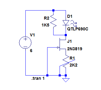
The current will depend on the transistor: with a BF245A it would be ~5mA, with a BF245C, 20mA.
The current will be almost independent from the supply voltage if it >5V
It is delightful to see complexity just to regulate 1 LED
Reminds me of a programmer I know that used a PIC processor to make a LED blink. I told him blinking LEDs can be bought just like that.
I too have also experimented with matters like these. Even the most sophisticated solution is redundant soon as one sets the LED to certain current and is satisfied. Then the current is measured and a simple resistor is enough. In my case 1 mA is enough for 3 mm green LED power on indicators. Not bright and not too dimmed. When fed DC LEDs do not blink and even with ripple the human eye won't see it. 230V AC fed LEDs in certain mains voltage switches don't even blink.
In my Corona amplifier I used pink/purple LEDs at a very moderate current only to see them changing color to blue in 2 days?!
Last edited:
LOL yes if I only did need to have the LED to glow with constant lumen, would this circuit maybe a bit much but it have to fulfill these functions:
1) It have to be able to dim the LED
2) Ripple shall not effect the LED in any way
3) If I chose to let the led glow in a certain lumen, shall it keep doing that, every single time.
I understand that the fet is adjusting max constant voltage and max current, and the turn pot then adjust the current down.
EDIT: Forgot to say that the LED is not ment to be looked at, but to adjust my no name lux-meter, so I can compare it against a known value.
EDIT: Forgot to say that the LED is not meant to be looked at, but to adjust my no name lux-meter, so I can compare it against a known value.
Quite essential info as some would think it is for the power on LED of an audio device.
Look here - jfet current source.But do you know the answer about my question in comment 35?
- Status
- This old topic is closed. If you want to reopen this topic, contact a moderator using the "Report Post" button.
- Home
- Design & Build
- Construction Tips
- Single diode dimmer - how?