Probably too late to ask seeing as I've spent some time today building this!
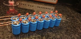
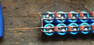
I have soldered up the cap bank for a 51Vdc supply for a tpa3255. Used 14 of 2200uF caps and for packaging purposes I have 2 rows of caps.
These are all aligned ground inwards, so the two inner copper wires are ground. One outer wire will be in from the bridge rectifier and the other outer will be the smoothed supply.
Have I made a potential ground loop with the physical looping of the wire around the caps.?
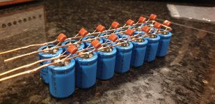
Attachments
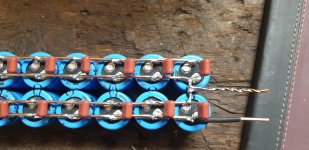
Yes, if you connect both ends of that wire. Better to have the outside wires separate,
and the two inner wires connected together (at the output).
You can cut that loop and reverse the two rows. Then you can join the inner rows and
attach an output lead to the join. This will be electrically the same as before.
and the two inner wires connected together (at the output).
You can cut that loop and reverse the two rows. Then you can join the inner rows and
attach an output lead to the join. This will be electrically the same as before.
Last edited:
Ah....so just leave one end of the ground wire unterminated ?
That would "work" but post #2 would be better. Alternatively, just use two electrically separate rows
(cut off the U at the far end), making the parallel connections at the rectifier block.
Last edited:
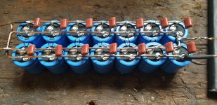
Better?!
I thought it all made perfect sense until I came to actually do it so I'm not sure I'm 100% there yet.
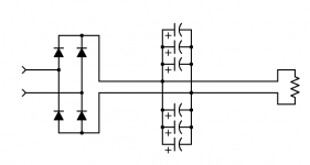
So assuming the pictures has the rectifier in from the left....load out to the right.
Positive rail 'loop' is removed from the output end.
Ground is still looped at right end and output connection tapped off the loop.
Maybe do I cut the loop at the input end?
Rectifier end positive feeds both Positve 'tracks'.
Am I heading in the right direction?
Thanks
I still have
I thought it all made perfect sense until I came to actually do it so I'm not sure I'm 100% there yet.
So assuming the pictures has the rectifier in from the left....load out to the right.
Positive rail 'loop' is removed from the output end.
Ground is still looped at right end and output connection tapped off the loop.
Maybe do I cut the loop at the input end?
Rectifier end positive feeds both Positve 'tracks'.
Am I heading in the right direction?
Thanks
I still have
Attachments
I think it (first pic) was ok - just use one pair as input and other pair as output.
"One outer wire will be in from the bridge rectifier and the other outer will be the smoothed supply." thats definitely fine, as it should be. Don't connect inner grounds together.
"One outer wire will be in from the bridge rectifier and the other outer will be the smoothed supply." thats definitely fine, as it should be. Don't connect inner grounds together.
Last edited:
- Status
- This old topic is closed. If you want to reopen this topic, contact a moderator using the "Report Post" button.
- Home
- Design & Build
- Construction Tips
- Single rail psu 2 rows of caps