Hi all
I bought a couple (actually 4) of Hood 1969 premade Class A amp boards from ebay. They are premade and have 6 screw terminals on them. They work at about 22-25v AC and I tried to mock up a mono amp with one of them. I should probably point out here the boards would be more than 10w.
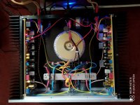
This was kind of hard as I needed to heatsink the boards. The boards are no longer on ebay but they are very similar to these ones with different 2 black caps in the middle and pre-adjusted POTs. I used a large aluminium heatsink and a 22-0-22v toroid to try and mock up one channel (click for zoom):
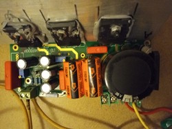
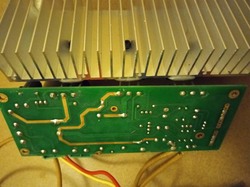
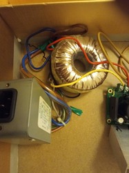
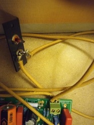
Please excuse the poor soldering - I have just got my station and it's not like a cheap iron. The speaker terminals are not shown used (I needed the wire). The mains block is from a Plasma TV and should provide some filtering as far as I know (I can remove this from the equation).
The result: bad. The amp board simply buzzed the speaker and did not amplify any input signal. I hope the method I used is clear from my pictures.
I have another 3 of these boards if the one I tried is now bad but I can't return it Any general advice or did I do something wrong? Experts unite!
I bought a couple (actually 4) of Hood 1969 premade Class A amp boards from ebay. They are premade and have 6 screw terminals on them. They work at about 22-25v AC and I tried to mock up a mono amp with one of them. I should probably point out here the boards would be more than 10w.
This was kind of hard as I needed to heatsink the boards. The boards are no longer on ebay but they are very similar to these ones with different 2 black caps in the middle and pre-adjusted POTs. I used a large aluminium heatsink and a 22-0-22v toroid to try and mock up one channel (click for zoom):
Please excuse the poor soldering - I have just got my station and it's not like a cheap iron. The speaker terminals are not shown used (I needed the wire). The mains block is from a Plasma TV and should provide some filtering as far as I know (I can remove this from the equation).
The result: bad. The amp board simply buzzed the speaker and did not amplify any input signal. I hope the method I used is clear from my pictures.
I have another 3 of these boards if the one I tried is now bad but I can't return it
Any general advice or did I do something wrong? Experts unite!
Last edited:
Moderators. Would be sensible to move this to the big Linsley-Hood Class A thread......that's where a large number of "Hoodies" hang out..
Cheers, Jonathan. https://www.diyaudio.com/forums/solid-state/3075-jlh-10-watt-class-amplifier-new-post.html
Cheers, Jonathan. https://www.diyaudio.com/forums/solid-state/3075-jlh-10-watt-class-amplifier-new-post.html
Don't forget the bolt collars.I have some mica on the way, about 25*22mm or so.
Don't forget the bolt collars.
I'm having trouble finding appropriate collars. I got 2 bolts + 1 10cm threaded rod (M3 [A2]) for affixing. Any advice? Maybe I would try with just masking tape otherwise - not good.
Some call them sleeves, some call them bushes, some sell them as a transistor mounting kit.
Got one! Looks abuout the right size. Will keep you posted with build progress.
I have built an amp prototype based on 2 1969 boards which are specced at 25w Class A each. The boards are currently listed on ebay similar.
Assembeld Hood 1969 MJE15024/25 Class A power amp board 25W 2 CH amplifier | eBay
This is the one I bought - almost the same... one pair left too.
I have a couple of questions:
1) The seller (after the build) recommended 2kg of aluminium heatsinking for the pair of boards. My heatsinks are only about 230g each. I could double up on them, double up on them and have 50% more heatsink on 2 of the 4 heatsinks, and probably try and use a fan to help with heat dissipation. Any thoughts on this? Is it going to be safe using the boards with just 460g - 900g Alu and a fan?
2) The transformer toroid I am using seems under spec. I am using an equivalent of 323-022 from this page:
Toroidal Transformer 80VA 0 - 22, 0 - 22 Transformers - Mains Toroidal
Obviously I am not getting the full 25w per channel with only 22v but I didn't realise enough that the toroid is only specced for 80w. I think I might be drawing more. Any way to be sure?
Any suggestions for alternative transformer for the pair of boards, or maybe 2 transformers?
The sound is very nice, rich, deep bass, controlled treble and a lot of body. It compares very well to the 60s Class AB Harmon Kardon A500 valve amp that I have (but is out of service at the moment). At least as good I would say - so I am pleased.
I have only tested the amp for up to an hour at a time before unplugging due to heat at the moment with 2 230g heatsinks (two of 200mm*69*37mm alu). They get pretty hot after this time, uncomfortable to touch.
Last edited:
I think the answer to all your questions is: It depends on the current setting in the amp. You could be able to use what you have, and set the current so everything works without overheating, and live with the limitation in output current (power).
It depends on the impedance and efficiency of the speakers you are using. If they are 8ohm with no serious dips, you don't need a high current, but if they are low impedance, you need higher current in your amp.
Try to set the current so the heat sinks stay around 50deg C, and then listen to it. Also check that the transformer is not getting hot. Not sure what the recommended max would be on that, but not more than the heat sink I would think. Maybe it will be able to play loud enough for your needs.
You do need a bigger transformer - 160va and, depending on your speakers, 24v will be too high as it will result in well over 30v on load.
18v would probably suffice if you can't find a 20 or 22v one.
I bought a pair of the higher power modules a few years ago and used 200 x 100x 40mm heatsinks and an 18v toroid.
They had a hard time driving my ML Aeon hybrid electrostatic speakers and although it sounded great - I'd echo your findings, it seemed to become hard and a bit harsh after a few minutes. I assumed it was just getting way to hot.
I did consider fan cooling, but I think the flaw is the thermal resistance of the L bracket.
I recently bought a pair of bare pbs and was going to rebuild them but using TO3p / TO247 transistors (Toshiba TC5200) bolted directly to a larger heatsink. Instead I've gone down the class A p-p Krell KSA50 clone route and the sound is comparable (from what I remember).
Last edited:
Thank you for the kind reply rallyfinnen.
I will check how many amps at 22v each board is using to see the current watts. I have no idea how to current limit the power amp boards if indeed possible so any tips on that would be great. All I can think is supplying them with less than 22VAC?
My speakers are Elac Debut F6 6 ohm and 87db sensitivity, rated for 150w. My room is not going to need more than about 12w of class A power anyway.
I do not have a bench power supply to test a board with max current setting.
Hope this helps
N
edit: Thank you for the reply batteryman. I am happy to try a fan. My heatsinks are a little smaller than yours and I used thermal interface material. If I double up on the heatsinks perhaps that will be enough - but I think it will be hard to limit these boards to a max operating temp of 50c... the L bracket is black anodised aluminium I think and there is heat transfer paste between the transistors and the bracket (and mica or similar insulators). If the flaw is really the L brackets that could be a big problem.
Last edited:
I recommend finding out what the DC voltage is and what current they have been set to. There should be preset for adjusting it.
If the heatsinks are at 50C, then the TO3 cans will probably closer to 70C. Did you use heatsink paste between the L bracket and heatsink?
My Aeons are quoted as 4r impedance, but dropping to 1.32r at 20khz and also are 89db sensitivity so probably a mistake to expect even the high power version to cope without more effective cooling - no L bracket and keeping the supply voltage down. (18v transformer)
Thanks again Batteryman. I did use thermal paste between the L bracket and the heatsink (though a little more on one than the other...). I am unsure how hot the heatsinks got after an hour of use but I would estimate they got to 70-80c.
I think to get these boards working stably I would need to get a 230v 160A > 18v*2 toroid, double up the heatsinks and probably use a 12v fan with a variable resistor to cool them (or maybe 2 fans) with a separate PSU.
I'll see if I can get my head around the board design or various circuit diagrams out there to check how many amps DC each board is using. Tips welcome.
For other readers, thanks for reading and if you have any input at all it's much appreciated. I'm new at this.
Last edited:
Best read all the articles on the Class A amplifier site:
The Class-A Amplifier Site
See if you can work out which schematic the Chinese have actually followed!
As regards the psu, personally I am not in favour of regulated supplies as they effectively mean there is another active device in series with the output transistors. Anyway with Class A amps taking a fairly steady current from the PSU, there should be no need for one. Just carefully choose the transformer. Most transformers specify the secondary volts at full load so 18v ac full wave rectified will give 25-27v DC.
Also your mains voltage will affect the volts - mine is not 230v, but 245-250 so a 230v specified 18v transformer will output 19v ac or as high as 28v DC. (on my Krell clone, the 250va 24v transformer is producing 36.6v on load)
Well, i sympathise with your problems.
Class A amplifiers need a lot of heatsinking. And power.
Typically they are 30% efficient, or at least that is a relatively safe estimate. Some may do better, of course. The JLH is such a design but might not get more than 40%.
That means for any given power output you need to be able to dissipate twice that in the transistors.
A reasonably good figure for the thermal resistance of mica (with silicone grease) is 0.4C/W. Some expensive silicone rubber with thermally conductive fillers may get to 0.2C/W.
The next component in the thermal path is the L bracket. If I take aluminium thermal conductivity as 238W/(m.K) a very rough estimate for the thermal resistance between the transistor is to assume half the width of the bracket (25mm for a 50mm side), a thickness - this is where the thickness is important - 3mm, and also that the effective width is the width of a transistor (in reality, the middle of the transistor gets hottest, but the heat will diffuse outwards as it spreads towards the bracket angle) of 30mm, that gives 1.17C/W. Each transistor may be dissipating 25W (if this is the RMS output power and not peak) and so far the total thermal resistance is 1.17+0.4(say)+whatever transistor thermal resistance is to the junction, which is around 0.7 for 250W class transistors, totalling around 2.3C/W. Which means on a (rough) estimate of (probably near worst case) scenario each device (junction) will heat up about 50-60C before even getting to the heatsink.
I'm guessing that the angle bracket is 3mm. It could benefit from being 5 or 6mm, is it?
It is important to use a heatsink which keeps the junction temperature within spec. (usually 200C for TO-3; only 150C for many "plastic" types like TO-264 though some do 175C).
The heatsink temperature depends on the surroundings: it needs free air circulation. Fans are not usually used in hifi setups because of the additional noise they generate, but if a fan means the difference between able to use it or not, I guess a fan is the only option, or reduce the power. From your comments, I suggest a reduced power might be beneficial in terms of transformer, heatsink and noise.
Note that the hottest part of the angle bracket will be at the angle. If you use silicone compound, make sure that part is coated well.
If you allow a 50 C rise on the heatsink, it means needing a heatsink thermal resistance of, if we say both transistors dissipating 50W in total (plus, I note, a power supply device. This is, as others have said, an added complication in terms of total power), you will need 1 degreeC/W or lower. It's not so much the weight of the heatsink as the thermal resistance, though the factors will be roughly inversely proportional. If your room temperature is 20 C then they will run at 70C, so you will need to make sure air can circulate. Commercially, a grill or perforated cage or some other means of preventing fingers touching such a heatsink would be needed. There are several sizes and designs of flat-based finned heatsinks which you might consider. Fischer is the name to look up.
Most importantly is to check the standing current (if you can) when the amplifier is at working temperature.
Once we know what your circuit actually is we can consider how to down size or otherwise suggest optimising.
On my Krell clone I am glueing a finned heatsink to each transistor as you can see in the photo - still some to do.
I checked the temp with a multimeter thermocouple and found the heatsinks dropped the temp from 70C to around 63C. The heatsink temp was around 50C, so 20C difference from TO3 can to HS fins. (each transistor is passing about 0.7 amp at 36v (per rail)
I checked the temp with a multimeter thermocouple and found the heatsinks dropped the temp from 70C to around 63C. The heatsink temp was around 50C, so 20C difference from TO3 can to HS fins. (each transistor is passing about 0.7 amp at 36v (per rail)
Attachments
- Status
- This old topic is closed. If you want to reopen this topic, contact a moderator using the "Report Post" button.
- Home
- Design & Build
- Construction Tips
- Help with Hood Class A board (mockup fail)