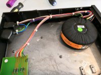
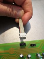
I'm repurposing a Naim power supply for the case and I want to reuse the Naim badge for the power indicator. It is connected to the original PSU using a small 6 pin molex ribbon connector.
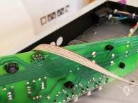
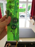
It looks like only 2 pins are connected to the track if you look at the back of the PCB even though all 6 pins are soldered.
I wondered if anyone could steer me in the right direction as to the best way to hook this up again. I'm going to be using the ULPS1225 PSU for my project.
When I get chance I'll open the case again and take a shot of the LED badge as I think it has a small PCB and resistor itself.
Attachments
-
 IMG_20190721_180035_resized_20190722_035656788.jpg775.5 KB · Views: 102
 -
 IMG_20190721_180103_resized_20190722_035656586.jpg561.5 KB · Views: 93
 -
 IMG_20190721_180615_resized_20190722_035657052.jpg553 KB · Views: 95
 -
 IMG_20190721_180633_resized_20190722_035656932.jpg697.9 KB · Views: 94
 -
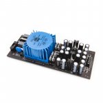 ulps1225_-e1561805025134.jpg63.7 KB · Views: 100
The connection closest to the edge of the PCB appears to be ground and the other looks like it's running at the V+ of the capacitor closest to the power wires. If you could measure that voltage, you can calculate if you need another resistor in series. The best way to proceed IMHO would be to de-solder the original connector from the PCB and extend it from the new psu to the connector using wires (and heat-shrink tubing).
- Status
- This old topic is closed. If you want to reopen this topic, contact a moderator using the "Report Post" button.