I had an issue with hum on my SHPA build (https://www.diyaudio.com/forums/gro...oupled-class-hpa-sub-ppm-thd-post5734161.html) which was rectified by installing a ground loop breaker to the input RCA - Chassis connection.
The SHPA has a Class II 12V SMPS input (I.E. not earthed). The chassis is floating at ~90VAC and this is common to several Plug Pack / Wall Warts that I have tried. I can feel the chassis 'vibrate' if I touch an earth with my thumb and run a finger across the chassis.
** Is it normal for a Class II Wall Wart to have ~90VAC (WRT Earth) on the Negative?
** Is the chassis of the Class II amplifier supposed to require an external grounding when connecting to a Class I device?
I know I can just make the connection and be done with it, but that doesn't help me learn what the cause is and how I can avoid this in the future. Any suggestions as to the cause would be appreciated!
The SHPA has a Class II 12V SMPS input (I.E. not earthed). The chassis is floating at ~90VAC and this is common to several Plug Pack / Wall Warts that I have tried. I can feel the chassis 'vibrate' if I touch an earth with my thumb and run a finger across the chassis.
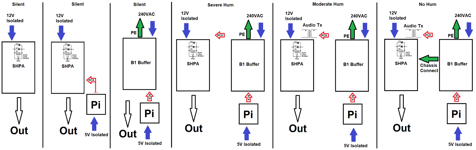
- I can connect an isolated source (for example RPi), and the amp is silent.
- If I connect an earthed source such as the Korg B1, I get severe hum.
- If I add transformer isolation to the RCAs, the hum is reduced.
- If I then connect the SHPA chassis to Earth, the amp is silent.
- Disconnecting the Earth from the B1 also eliminates the Hum.
** Is it normal for a Class II Wall Wart to have ~90VAC (WRT Earth) on the Negative?
** Is the chassis of the Class II amplifier supposed to require an external grounding when connecting to a Class I device?
I know I can just make the connection and be done with it, but that doesn't help me learn what the cause is and how I can avoid this in the future. Any suggestions as to the cause would be appreciated!
Attachments
Is it normal for a Class II Wall Wart to have ~90VAC (WRT Earth) on the Negative?
I hope not, even if it's at a high impedance. Get one that doesn't do that.
High-frequency switchers "must" have RF suppression or they wipe-out TV signals.
On a 2-pin plug, the *only* way they can do this is two (often 0.005uFd) caps from their internals to the two pins.
On a 230V power line, an infinite-impedance meter will read 115V from internals to either power pin.
Since one power pin ("N") is normally near-"ground", this appears as "115V to ground".
0.005uFd at 50Hz is 636k impedance.
You report measuring 90VAC. This appears to imply that your *meter* is about 2.2Meg. 2Meg is not uncommon for the ACV range of medium-price DMMs. Put your body (better!! a 100K resistor) across the meter, you will find much lower voltage.
The maximum "shock current", worst-case, is 230V/636k or 0.04mA. This is generally far below any "safe" limit for residential use. (Open-heart surgeries may ask for lower.)
There's no really-good answer beyond finding 3-pin warts. If you let the part-mA of 50Hz flow through your audio path grounded at the most sensitive end (typical) then it is liable to induce microVolts of hum. Breaking ground ("loop breaker") is often done.
SMPS's have strong coupling at the switching frequency between primary and secondary due to stray capacitance and high voltage and frequency. If this high freq isn't decoupled to something the output will be a powerful RF source _and_ a definite shock hazard. Typical stray capacitances of the order of 100pF can be countered by decoupling which will drain the lethal ~10mA at the switching freq, but then that leaves 5nF or so at mains frequencies if an earth terminal isn't available, leading to a fraction of a mA mains leakage, which is quite detectable as a tingling.
That paragraph was too long!
Basically an isolating transformer isn't that isolating at 100kHz and 240V without an earthed screen...
That paragraph was too long!
Basically an isolating transformer isn't that isolating at 100kHz and 240V without an earthed screen...
- Status
- This old topic is closed. If you want to reopen this topic, contact a moderator using the "Report Post" button.