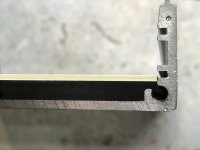
I've just had some boards made but for whatever reason (probably my mis-measurement  ) they've come out under-size for the extruded enclosure.
I need a solution that will retain the board securely in the runners whilst being removable.
This is a DIY project so it doesn't have to be perfect, but not too tatty either.
The board has 4 transformers mounted on it, and mains tracks on the bottom, so the securing method needs to be strong.
Thanks
Not shown in the picture, the other side has the board fully into the runners.
) they've come out under-size for the extruded enclosure.I need a solution that will retain the board securely in the runners whilst being removable.
This is a DIY project so it doesn't have to be perfect, but not too tatty either.
The board has 4 transformers mounted on it, and mains tracks on the bottom, so the securing method needs to be strong.
Thanks
Not shown in the picture, the other side has the board fully into the runners.
Attachments
Thanks for the suggestion, it would certainly work.
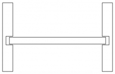
Thinking more about it, I'm wondering if I can pack each grove with a spacer that's accurate enough to keep it central.
The question is thinking about an off-the-shelf item that might work 1.6mm x 0.8mm x 230mm...
Thinking more about it, I'm wondering if I can pack each grove with a spacer that's accurate enough to keep it central.
The question is thinking about an off-the-shelf item that might work 1.6mm x 0.8mm x 230mm...
Last edited:
Try again:
An externally hosted image should be here but it was not working when we last tested it.
Thanks for the suggestion, it would certainly work.
Thinking more about it, I'm wondering if I can pack each grove with a spacer that's accurate enough to keep it central.
The question is thinking about an off-the-shelf item that might work 1.6mm x 0.8mm x 230mm...
You could use layers of aluminium tape in the grooves if you have enough meat left on the PCB to have it suspended in the groove when central.
Put the tape in the groove, then use the edge of a wooden icecream stick to smooth. Cut away the excess with a scalpel or fresh Stanley blade and repeat equally on both sides.
With mains tracks involved, don't take chances of it moving eg in worst case of being dropped.
Transformers are usually heavy.
You could cut an insulating board to the correct width to fit the slots, screw the pcb to that using stand-offs. Probably the most expensive option but it would look as if an intended design.
If not, consider spacers or insulation to prevent accidental contact of mains with case.
Thank you for the suggestions, much appreciated. I'm constrained vertically by the "lytics that touch the top, and the distance between the cut component wires and the base.
It may be that a combination of avtech23's idea of the 'ally tape and some insulated pads to space the PCB and prevent it from touching the base may work. I'll let you know.
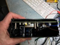
Attached are a couple of pix that illustrate.
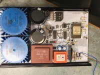
What is it? It's monoblock motherboard to take Pete Millet's Nutube class D amp (mounted on the pillars). Apart from supplying power to the amp, it has an audio sensor for auto power up/down using a SS relay with preset timeout. Also an isolated DC power supply for my Martin Logan electrostatic speakers - yes I'm a couple of caps short for that bit. It takes balanced via an LL1540 and unbalanced in. The reason the large bridge rectifier is connected via a terminal block is that I'm intending to fit an active bridge rectifier, as described in one of our DIYaudio group buy threads as soon as available.
I don't do SIMs or breadboards. Fortunately this one 'just worked" so I can't justify getting the boards re-made.
It may be that a combination of avtech23's idea of the 'ally tape and some insulated pads to space the PCB and prevent it from touching the base may work. I'll let you know.
Attached are a couple of pix that illustrate.
What is it? It's monoblock motherboard to take Pete Millet's Nutube class D amp (mounted on the pillars). Apart from supplying power to the amp, it has an audio sensor for auto power up/down using a SS relay with preset timeout. Also an isolated DC power supply for my Martin Logan electrostatic speakers - yes I'm a couple of caps short for that bit. It takes balanced via an LL1540 and unbalanced in. The reason the large bridge rectifier is connected via a terminal block is that I'm intending to fit an active bridge rectifier, as described in one of our DIYaudio group buy threads as soon as available.
I don't do SIMs or breadboards. Fortunately this one 'just worked" so I can't justify getting the boards re-made.
Attachments

How about put 1mm dia. x 230 mm round rod/tube on both side of grooves?
ROUND tube/1mm OD-Metalliferous
ROUND tube/1mm OD-Metalliferous
JMFayey has the best suggestion. Find some areas that you can use short standoffs to secure the board to the bottom of the enclosure. That is an amp board so I'm sure it has a bit of current usage and it really needs to be secured well. With those heavy transformers I wouldn't be looking for short cuts. And measure twice/cut once next time.
BillWojo
BillWojo
I agree with that too considering what is contained on the board.
Looking at the board, there are already some standoffs being used so you could drill and tap some holes aligned with those (and others as required to achieve a rigid fit), get some short (10mm say) standoffs and thread those down into the chassis with some threadlock (Loctite 222 or even Superglue for instance). Then you can place the PCB, thread the next set of standoffs on top. When you place your final layer of pcb on top, affix with M3 screws.
Board will still be removable but via lifting the top cover instead of sliding from the rail.
Hi,
depending on the clearances, have you thought of getting a piece of fibreglass sheet (with no copper on it) that does fit the grooves and then using some very small standoff to secure your pcb to it. You could probably just use a plastic nut as a spacer.
This arrangement would also provide another barrier between the mains voltages on the card and the case.
Regards,
Mike
- Status
- This old topic is closed. If you want to reopen this topic, contact a moderator using the "Report Post" button.
- Home
- Design & Build
- Construction Tips
- PCB to Enclosure fit problem