How is internal wiring done when there's no common ground chassis, to avoid ground loops and interference, and when there are multiple boards that have to be connected between them and between their inputs/outputs and external connectors.
I'm mainly concerned about line level signal wires that are most likely to pick up noise. Should I use shielded wires, or are there any specific techniques?
I'm mainly concerned about line level signal wires that are most likely to pick up noise. Should I use shielded wires, or are there any specific techniques?
Right, so I did all the line level connections using shielded wire and I still get noise.
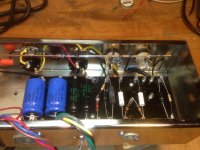
The amp is made of two crossover boards and two amplifier boards (one for each channel).
The amps are dead silent (with the input disconnected), so the noise comes from the crossovers (both), even with their inputs disconnected.
I'll poke around with the scope to see where it picks up the noise.
The amp is made of two crossover boards and two amplifier boards (one for each channel).
The amps are dead silent (with the input disconnected), so the noise comes from the crossovers (both), even with their inputs disconnected.
I'll poke around with the scope to see where it picks up the noise.
Old style answer (which I used a lot on prototypes and is still popular on Guitar Tube amps) was to use a "bus bar", a thick copper wire, (say, 1 to 1.2 mm diameter) and naked, preferably tinned, wich goes where needed to provide a ground reference, and to which ground returns are soldered.
If you are somewhat careful it may work very well.
EDIT:
Problem is that "ground" is not "GROUND", meaning points you ground to are not perfect or "clean" by any means, even if a meter reads a dead short between 2 points, resistance and inductance is not zero and sometimes ground can be quite dirty, meaning there is some AC signal where in theory there shoud be none, and grounding there injects hum/noise into a previously clean input.
Typical example and a very common one: suppose you ground main filter caps to a chassis point (or track or wire) and power transformer center tap or ground return wire to another chassis point, a couple inches away.
Resistance between both chassis points may be 0.01 ohm (1 hundredth of an ohm) but transformer may be passing 10A peak current pulses, 100/120 times a second, to charge filter caps.
Such current is not sinusoidal but made up of narrow peaks.
You will develop 10A*0.01 ohm= 100mV peaks and if you ground your input there, you end up injecting 100mV peak buzz into your signal
Not an extreme example by far, it happens all the time and *some* of that is most probably happening to you.
You must be careful with ground returns, where you ground low signal level stages (which are the most sensitive), often grounding "here" is buzzy/noisy Hell and "there" (1 inch away) is silence Heaven.
Any high current path is suspect, same with speaker return grounding.
"In principle" best ground is at main filter caps ... but you have to reach there first, and path is very important.
It´s "almost" a Black Art ... or to be more precise, "practice makes perfect" ... my first amps all buzzed, oscillated, hummed, the works , even using extreme measures such as shielding filament wires.
Today? ... I often use desk lamp grade zip cord and get away with it
If you are somewhat careful it may work very well.
EDIT:
Shielding is just half of the problem, equally (or even more) important is grounding, you´ll have to experiment with that.I did all the line level connections using shielded wire and I still get noise
Problem is that "ground" is not "GROUND", meaning points you ground to are not perfect or "clean" by any means, even if a meter reads a dead short between 2 points, resistance and inductance is not zero and sometimes ground can be quite dirty, meaning there is some AC signal where in theory there shoud be none, and grounding there injects hum/noise into a previously clean input.
Typical example and a very common one: suppose you ground main filter caps to a chassis point (or track or wire) and power transformer center tap or ground return wire to another chassis point, a couple inches away.
Resistance between both chassis points may be 0.01 ohm (1 hundredth of an ohm) but transformer may be passing 10A peak current pulses, 100/120 times a second, to charge filter caps.
Such current is not sinusoidal but made up of narrow peaks.
You will develop 10A*0.01 ohm= 100mV peaks
and if you ground your input there, you end up injecting 100mV peak buzz into your signal Not an extreme example by far, it happens all the time and *some* of that is most probably happening to you.
You must be careful with ground returns, where you ground low signal level stages (which are the most sensitive), often grounding "here" is buzzy/noisy Hell and "there" (1 inch away) is silence Heaven.
Any high current path is suspect, same with speaker return grounding.
"In principle" best ground is at main filter caps ... but you have to reach there first, and path is very important.
It´s "almost" a Black Art ... or to be more precise, "practice makes perfect" ... my first amps all buzzed, oscillated, hummed, the works , even using extreme measures such as shielding filament wires.
Today? ... I often use desk lamp grade zip cord and get away with it
Attachments
Last edited:
Ah, that sounds like the loop is through the power 0V. Is it commoned between the crossovers and amp?Edit: by no change I mean that the noise is still there, but the speaker with no power on the crossover is silent.
The center tap is common for both the high voltage rails and the low voltage rails (that's how the transformer is built).
I only left a crossover board with only one output connected and ran a thick wire directly to the center tap of the transformer. The buzzing goes away, but there's some faint mains hum.
I only left a crossover board with only one output connected and ran a thick wire directly to the center tap of the transformer. The buzzing goes away, but there's some faint mains hum.
Heat
While not related to the noise/hum issues, that will presumably be sorted out, not mentioned yet is whether the top cover is perforated to allow for heat dissipation. I’d be concerned about that in the long term, and even suggest an array of holes on the bottom in the immediate vicinity of the heat sinks to facilitate a chimney effect. I’ve built more than a couple of wooden sleeves for vintage tube pre-amp/ tuners, amps and receivers, all of which were ventilated on both top and bottom.
Regardless of the technology, heat and time are your enemies - ask anyone with an older Mac Mini. No matter what else might be said about metal chassis, they can help with heat dissipation by conduction and radiation.
With proper ventilation / passive dissipation, forced cooling may not be necessary. There are reasons that finned heat sinks are frequently seen on the sides of chassis. I’ve always been a fan of as few boxes / interconnects as possibly, and would be inclined to keep them in the same package. With perhaps some reconfiguration of component placement, as well as other techniques gleaned from suggestions in this thread, you could both eliminate noises and arrive at a compact tidy build.
The general rule with unbalanced signal wiring is that the ground must follow the signal. That may sometimes mean that the signal wire shield is what actually delivers the ground connection to a circuit; if so, nothing else should do this as well to avoid ground loops. Unfortunately PSU design (sometimes forced by ignorant transformer makers) sometimes forces a ground connection there, which can be about the worst possible place to join grounds together.
- Status
- This old topic is closed. If you want to reopen this topic, contact a moderator using the "Report Post" button.
- Home
- Design & Build
- Construction Tips
- Internal wiring in wooden chassis