I'm baffled.
If you build a solid amplifier with a star 0V it will work flawlessly.
I've also got a pre-amp with a solid star 0V and it works flawlessly.
Connect the two together and you invariably end up with a loop.
I've got a commercial CD player which I'm not going to modify.
I thought breaking the loops in the pre might do the trick but it hasn't.
The question is where to break the loops.
If both units share a common earth ground then you may need to break the grounds on both of the input cables.
Leaving the shield connected on one end.
If you are using a shielded twist pair cable and breaking the shield connection on one side doesn't help then you may also have to break the signal ground wire as well.
Leaving only the Hot signal (Red) wire to feed the amp with.
The wire will still be quiet as its shield and will be still connected to ground but only from one side.
Imagine learning that the hard way with a 32 channel mixer complete with a 60+ channel patch bay and 16 track recorder!!!")
In the past I have even found that some pieces of equipment that have a non-polarized plug can induce hum in to the system and just flipping the plug over (180 degrees) and plugging the unit back in can solve the issue as well.
It is good that the chassis are earth grounded but the signal grounds should not be connected to chassis and this is sort of a non-standard practice as some manufactures equipment follow this rule, and, some don't.
FWIW
jer
Leaving the shield connected on one end.
If you are using a shielded twist pair cable and breaking the shield connection on one side doesn't help then you may also have to break the signal ground wire as well.
Leaving only the Hot signal (Red) wire to feed the amp with.
The wire will still be quiet as its shield and will be still connected to ground but only from one side.
Imagine learning that the hard way with a 32 channel mixer complete with a 60+ channel patch bay and 16 track recorder!!!
In the past I have even found that some pieces of equipment that have a non-polarized plug can induce hum in to the system and just flipping the plug over (180 degrees) and plugging the unit back in can solve the issue as well.
It is good that the chassis are earth grounded but the signal grounds should not be connected to chassis and this is sort of a non-standard practice as some manufactures equipment follow this rule, and, some don't.
FWIW
jer
Last edited:
The star ground you build into the amp helps prevent ground loops within the amp. But you are creating ground loops in the traditional spot - between pieces of gear. Your two units are both grounded to the mains, but up at their chassis, there is a difference in potential between them, and when a signal cable connects them together, it creates the loop as AC current flows through the cable shield, which is grounded at both ends.
There are commercial loop killers, which amount to an isolation transformer, so the signal passes unit to unit without a direct connection.
The dirty way is to lift the mains ground on one unit.
And yes, try a patch cord with the shield only connected at one end.
There are commercial loop killers, which amount to an isolation transformer, so the signal passes unit to unit without a direct connection.
The dirty way is to lift the mains ground on one unit.
And yes, try a patch cord with the shield only connected at one end.
Take care if interfering with your chassis earth. Read Rods page for some good guidelines.
Earthing (Grounding) Your Hi-Fi - Tricks and Techniques
Earthing (Grounding) Your Hi-Fi - Tricks and Techniques
I'm baffled.
If you build a solid amplifier with a star 0V it will work flawlessly.
I've also got a pre-amp with a solid star 0V and it works flawlessly.
Connect the two together and you invariably end up with a loop.
I've got a commercial CD player which I'm not going to modify.
I thought breaking the loops in the pre might do the trick but it hasn't.
The question is where to break the loops.
You've probably seen this before but it does no harm to repeat it,
http://www.diyaudio.com/forums/soli...-lin-topology-nfb-tappings-2.html#post1624677
Have a read at all my posts in the thread.
Both the Source and the Amplifier are two channel.
The connection between them is a two channel interconnect.
One interconnect is a two wire connection of Flow and Return. The voltage difference at the Receiver end is amplified and sent to the output.
The other interconnect is also a two wire connection of Flow and Return.
If the returns (Signal Ground) are connected to a common reference at both ends, you have a grounding loop.
The bigger the area in that loop the more interference it will pick up.
It would be really nice if they made a dual coax with the outer of the coax forming an electrically conducting figure 8. That would allow the two returns to have near zero loop area.
I have not seen such a cable, nor have I seen a coax connector that would be compatible with the fig 8 screens.
I suggested that part of the solution would be for Source or Receiver to NOT use a common reference for both channels. I was told "don't be stupid": all Sources have a common Signal Ground reference.
The ground lifting using a resistor (and maybe the inverse parallel diodes) in each Source Signal Ground to Ground reference could maybe be a workable solution.
Close coupling of the two inter connects should help attenuate.
Two forms of attenuation: the ground lifting resistor and the low loop area are better than none.
Certainly a pair of monoblocks solves this, at the cost of separate chassis.
Finally,
the PE connection of the Chassis, or both Chassis, has NOTHING to do with that Signal Return Grounding Loop.
Last edited:
The signal return route is part of the two wire connection. You must not break that return route.
If you do break that signal return route, either the interconnect will not work, or the signal will find another route to complete the circuit.
That discovered route will almost certainly have an enormous loop area, since it is no longer close coupled with the signal flow.
Remember all circuits are a loop. That circuit demands that current starts from the source emf and returning to that same emf. If the loop area is big then the loop picks up more interference.
To avoid that we close couple the flow and return to minimise the loop area.
BTW,
a screen that is NOT carrying signal can be connected at one point.
At VHF, it is usually better if it is connected at all ends.
Last edited:
have you tried grounding to chassis the 0V of the power amp?(Crest series commercial amps used to come equipped with a removable link in multi way systems this allowed lifting or linking)
if indeed both your pre-amp and power amp are floating can you expect it to be quiet?(there has to a ground reference somewhere star-point or otherwise)
if indeed both your pre-amp and power amp are floating can you expect it to be quiet?(there has to a ground reference somewhere star-point or otherwise)
I'm baffled.
If you build a solid amplifier with a star 0V it will work flawlessly.
I've also got a pre-amp with a solid star 0V and it works flawlessly.
Connect the two together and you invariably end up with a loop.
I've got a commercial CD player which I'm not going to modify.
I thought breaking the loops in the pre might do the trick but it hasn't.
The question is where to break the loops.
In case you have two class I instruments (PE connected with signal ground) and single-ended signal interconnections, some degree of hum (even if inaudible but measurable) is inevitable.
Possible cures:
1) fully balanced interconnection
2) single ended interconnection, but with link transformer between preamp and amp
3) only one of the all instruments is in class I
4) isolation transformer for power supply of at least one of the instruments
Any of 4 advices will work.
Yes.are the rca (signal grounds)isolated from the chassis earth?
But the amplifier needs a voltage reference to tie the output to the input.
This is a single wire reference link.
This link must be close coupled to the wires most sensitive to picking up interference.
If you mean the connection to Mother Earth, then no improvement to audio quality and sometimes a reduction in quality.Do i get better SQ with earth ground? Any experience?
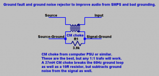
Try this. Before you say it, no, it doesn't cause any distortion whatsoever because it never reacts to the signal. It only reacts to common mode signals so the most it can do is fail to reduce a little ground noise (which still leaves you better off than a groundlift resistor would).
This is the kind of thing you want:
http://www.mouser.com/ds/2/355/DS_EV-EHseries_20110616_web19-8801.pdf
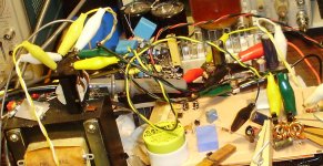
The photo has one on the left I got from a projector TV.
This is the kind of thing you want:
http://www.mouser.com/ds/2/355/DS_EV-EHseries_20110616_web19-8801.pdf
The photo has one on the left I got from a projector TV.
Attachments
Last edited:
- Status
- This old topic is closed. If you want to reopen this topic, contact a moderator using the "Report Post" button.
- Home
- Design & Build
- Construction Tips
- Ground Loops