As I guess a lot of people have done, I'm building an amplifier into a steel chassis.
The amplifier in question is a Pass F5 so things are expected to get a bit warm.
Now, I've got two huge heatsinks which should dissipate the heat.
My question is - how will the steel reduce the effectiveness of the heat transfer ?
i.e. I'll have Tj -Cs - Steel - Heatsink.
I know that I'd be better cutting two huge holes in the steel to mount the MOS-FETs directly onto the heatsinks but is this really necessary?
Hi,
It all depends on real physics, noting most transistors have steel tabs.
The physics indicate cutting holes in the steel sheet is pointless, why
you will never see it in a commercial amplifier. The layer is thin and
very spread so will likely have less effect than the insulator layer.
At the same time steel has a high thermal capacity, so although
long term it will reduce maximum heat flow, short term it will
increase it, and simply put the thicker the layers the output
trannies are attached to the better they are at spreading heat.
I'd say all in all its simply not necessary to cut any holes for
typical heatsinks but there is a point with very serious
heatsinks where it might make sense, usually doesn't.
I'd say most of the time its heat spreading ability is useful,
but that of course also depends on the heatsink design.
rgds, sreten.
Don't be diverted from protecting your junction temperature. Its an F5 you are building for goodness sake, not some relic with steel TO3's.
Every intervening material between junction and ambient adds 2 sets of thermal resistance. The wiser path is to minimise the thermal resistance. But I see your problem, its an ugly shaped heatsink to attach to the outside of a case, have you considered an alternative thats easier to mount?
Every intervening material between junction and ambient adds 2 sets of thermal resistance. The wiser path is to minimise the thermal resistance. But I see your problem, its an ugly shaped heatsink to attach to the outside of a case, have you considered an alternative thats easier to mount?
I disagree completely and absolutely with sreten on this one.
Steel is a lousy conductor of heat compared to aluminum.
The greater number of transitions between materials the worse the thermal conductivity.
The F5 runs in real Class A, so there is real heat, unlike a low bias Class AB or B.
One would like to maximize the transfer efficiency given the temperature inside the Mosfets.
Which is essentially what Johno just said.
I'd cut holes in the side of this steel chassis large enough to permit a very wide window, as much as 100% or better for the heatsink's rear side (assuming a flat back heatsink?).
The heatsink needs to have a clear path for airflow from below to above the fins, and (imho) an airpath on the back side as well.
The heatsink can easily be mounted using auxiliary hardware, parts as required. Whatever is required or usable.
You need fairly massive heatsinks for the F5.
Bigger if you go above the stock power rating of ~20watts per channel.
In general the cooler the devices can stay the better the thermal stability and the higher the SOA will be as well.
I'd mount the heatsinks, using the tabs already in the extrusion, by putting them on some
standoffs - physically float the heatsink off the chassis so there is easy airflow.
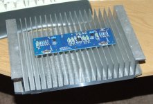
How about some pix of the chassis??
Steel is a lousy conductor of heat compared to aluminum.
The greater number of transitions between materials the worse the thermal conductivity.
The F5 runs in real Class A, so there is real heat, unlike a low bias Class AB or B.
One would like to maximize the transfer efficiency given the temperature inside the Mosfets.
Which is essentially what Johno just said.
I'd cut holes in the side of this steel chassis large enough to permit a very wide window, as much as 100% or better for the heatsink's rear side (assuming a flat back heatsink?).
The heatsink needs to have a clear path for airflow from below to above the fins, and (imho) an airpath on the back side as well.
The heatsink can easily be mounted using auxiliary hardware, parts as required. Whatever is required or usable.
You need fairly massive heatsinks for the F5.
Bigger if you go above the stock power rating of ~20watts per channel.
In general the cooler the devices can stay the better the thermal stability and the higher the SOA will be as well.
I'd mount the heatsinks, using the tabs already in the extrusion, by putting them on some
standoffs - physically float the heatsink off the chassis so there is easy airflow.
How about some pix of the chassis??
Last edited:
I disagree completely and absolutely with sreten on this one.
Hi,
Well back it up with some real physics assuming typical steel
cased or tabbed devices, I know why steel is good enough.
You have completely missed the points I made earlier.
Which make a lot more sense than dogma.
It depends on the heatsink design whether a steel
layer is better or not, not just it must be worse.
rgds, sreten.
Last edited:
The Pass amps are Class A, and require all the heatsink they can muster. I've even spent time lapping (with 1200 grit sandpaper) the heatsink tabs on MOSFETS (and mounting areas on the heatsinks--particularly around any drilling flash) to insure the best possible MOSFET to heatsink contact. That and the use of mica (and grease) or kerafoil will also be needed.
Do NOT mount the MOSFET on (or directly through) the steel chassis--significantly cuts down the efficiency of the heatsink, and your MOSFET temperature will show that.
If you MUST mount the heatsink to a steel chassis, first locate and mark the location of the semi's on the chassis. Then remove the semi's from the steel, and cut a 1-1/2 to 2 inch circular hole (use a hole saw or a Greenlee chassis punch. Replicate the locations of the semi's on the heatsink, and you'll be OK. In effect, you have the semi mounted on the heatsink, with the steel having a large hole in it, to allow you do do this. (Just remember you can't wire--and test--the amp, until you have the semi-steel-heatsink "sandwitch" assembled(!)
I can't find the reference I was thinking of, but these links should substitute.Well back it up with some real physics assuming typical steel
cased or tabbed devices
List of thermal conductivities
Properties of metals
I like CanAm Man's last suggestion, as the finned side of the heatsink has much greater surface area and is where most convection will occur.
Hi,
Somebody quote some real numbers rather than talking crap.
rgds, sreten.
Real numbers for a steel output device via a steel chassis to
an aluminium heat sink are such its hardly worth the effort.
An aluminium heatsink designed to fit a steel case will
typically take into account the heat spreading of the
steel layer, for such a heatsink directly mounting
devices has no real benefit, it may be worse.
Hi,
Somebody quote some real numbers rather than talking crap.
Built a bunch of Class A amps, have ya, sreten?
I have. And also a number semiconductor 1-kilowatt HF and VHF power amps.
Funny, but when we want to improve thermal coupling between power semi's and a large heatsink area, we use thick COPPER bar stock as a heat spreader. Next best engineering practice is to "direct mount" the semi on the heatsink.
If you desire to use steel as a medium between a semi and a heatsink, please do. Please send pictures of the finished product, when you fire it up under load. ("Fire it up" is probably an accurate description)
I won't bore you with my background in physics and thermodynamics. Besides, I'm not going to sway your opinion, am I?
I can't find the reference I was thinking of, but these links should substitute.
List of thermal conductivities
Properties of metals
Hi,
Quoting facts is no substitute for understanding the physics,
and that you have implies you don't understand the physics.
rgds, sreten.
Heat sink - Wikipedia, the free encyclopedia
If you can't follow the transition equations, there are some pictures that might amuse you..........
If you can't follow the transition equations, there are some pictures that might amuse you..........
Getting competitive performance through a steel chassis is harder than making some holes in it.
Yep...that's why you do NOT want to sandwich a steel chassis between a semiconductor and it's heatsink. Q.E.D.....
Before I continue reading the replies I'd like to respond.Hi,
Quoting facts is no substitute for understanding the physics,
and that you have implies you don't understand the physics.
rgds, sreten.
I've yet to see your numbers, and until I do I'd appreciate you keeping the personal comments to yourself. Thank you.
Built a bunch of Class A amps, have ya, sreten?
I have. And also a number semiconductor 1-kilowatt HF and VHF power amps.
Funny, but when we want to improve thermal coupling between power semi's and a large heatsink area, we use thick COPPER bar stock as a heat spreader. Next best engineering practice is to "direct mount" the semi on the heatsink.
If you desire to use steel as a medium between a semi and a heatsink, please do. Please send pictures of the finished product, when you fire it up under load. ("Fire it up" is probably an accurate description)
I won't bore you with my background in physics and thermodynamics. Besides, I'm not going to sway your opinion, am I?
Hi,
No because your being an idiot. As I've said all along it depends
on design what is best, here it simply whether its worth it or
not to bypass the steel case and IMO it basically usually isn't.
The real physics indicate a minor loss of heat flow.
Don't try and tell me how to implement a "heat spreader",
that you think you can just shows how little you really know.
rgds, sreten.
Last edited:
- Status
- This old topic is closed. If you want to reopen this topic, contact a moderator using the "Report Post" button.
- Home
- Design & Build
- Construction Tips
- Heatsinks