I was really suprised to learn that diamond is such a wonderful conductor of heat.
In fact, that's how many jeweler's/gemsetters quickly check a diamond, vs. moissanite and other synthetics. They use a small heat probe, and the probe's temp drops relatively quickly when touched to a diamond. Easy, peasy.....
No, that isn't what I'm saying, and you're response has nothing to do with what I wrote.Ok, place a thermal insulator sheet over the backside.
Compare the device temp in that case to the one where the backside has free convective air flow.
Are you saying that the temps will be the same?
Diamond heatsinks are in use for specialised applicationsMainly in RF but the synthetic diamonds are appearing in other applications these days.
Heatsinks
Someday I'll be about to tell you'all a "business story" about depositing a SiC gigahertz power transistor on a platinum-diamond substrate, and attempting to do "thermal management" in the vacuum of space. What a challenge.....
More to follow, if the details are ever released to the public......
No, that isn't what I'm saying, and you're response has nothing to do with what I wrote.
Ah gee.
You said the backside is the entry point, so it is "expected" to be the hottest. Right?
Hottest, yes, locally near the device, actually *at* the point of contact.
Then what? Eh?
The heat goes where? Only out to the fins?
There is "hottest" but also less "hottest" and most "hottest". And done wrong, there is too very much "hottest".
I said if you have airflow across the rear face of the heatsink, and over the devices, that the temperature will be *lower* and more heat will be transferred to the air than in the other case where there is no airflow and the rear side of the heatsink is in essence unable to transfer heat to the air and the *only* efficient path is out the other side to the fins...
Not sure how that doesn't work with what the topic of converstation is/was and what you appeared to have written?
Please explain your position, and where Mr. Fourier and you are going with this? Was his post deleted, guess I didn't see him in here.
_-_-
It's also useful to note that "you're" is a contraction of "you are", I think you meant to say "your" which is either the second person or fifth person in English.
Last edited:
You seem incapable or unwilling to discuss the posts in question. My view is that anyone should be able to read my posts in this thread and answer your questions above without further help from me.Ah gee.
You said the backside is the entry point, so it is "expected" to be the hottest. Right?
Hottest, yes, locally near the device, actually *at* the point of contact.
Then what? Eh?
The heat goes where? Only out to the fins?
Sometime when I'm truly bored I'll check if the above is the equivalent of your previous post. I have serious doubts.I said if you have airflow across the rear face of the heatsink, and over the devices, that the temperature will be *lower* and more heat will be transferred to the air than in the other case where there is no airflow and the rear side of the heatsink is in essence unable to transfer heat to the air and the *only* efficient path is out the other side to the fins...
Not sure how that doesn't work with what the topic of converstation is/was and what you appeared to have written?
My position should be obvious.Please explain your position, and where Mr. Fourier and you are going with this? Was his post deleted, guess I didn't see him in here.
Your attempt at sarcasm is imbecilic, not humorous, enlightening, or persuasive.
_-_-
I saw the mistake and didn't feel it required a post dedicated to correction.It's also useful to note that "you're" is a contraction of "you are", I think you meant to say "your" which is either the second person or fifth person in English.
It isn't nearly as bad as, "And done wrong, there is too very much "hottest"."

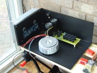
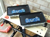
Only the other half to build now.
that should do it.... make certain you use either (1) mica + grease, or (2) kerafoil for best heat transfer between the MOSFET and heatsink.
Also "bond" the small thermistor "bead" to the MOSFET tab or on the heatsink, very close to the MOSFET. The bead must be able to closely track the temp of the MOSFET.
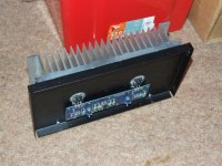
The heatsinks look a little "small-ish" for an F5, but hard to tell without a scale for reference. Just watch your bias and MOSFET temp as you start it up. You might want to start a Pass Labs forum thread on your build, if you are looking for comments from experienced F5 builders.
The heatsinks are approx 300mm wide x 180mm tall x 70mm fin height.
QUOTE]
That's roughly the size of the Conrad heatsinks I used on my F5, so you should be in good shape. Just watch your bias and temps for the first hour or so, when you fire up your F5 and tweak the bias voltages.....
Good luck......
They should be adequate as this is only the HF amp in a tri-amp system.
If you ever doubt about cooling consider to get them anodized black.
This will help dissipation by some percent.
My question is - how will the steel reduce the effectiveness of the heat transfer ?
The real problem is not steel versus aluminum, it's the crossing between two layers which is the thermal resistance bottleneck.
Using two different materials merely adds to the thermal problem.
Aluminum has twice the thermal expansion factor of steel.
For a 10'' length and 30C temperature rise, difference in elongation would be about 1/100th of an inch.
That may seem very little, but the implication is that the aluminum heatsink and the steel chassis panel move with respect to eachother, in their contact plane.
Result is that there will always be a tiny air gap between the two, and stationary air is by far the best thermal insulator.
Heat transfer and fluid mechanics 101 (unlikely to be taught to EE students)
Last edited:
PS, for some RF type amps a copper "spreader plate" is required because even a direct connection to the aluminum isn't sufficient.
Built a bunch of Class A amps, have ya, sreten?
I have. And also a number semiconductor 1-kilowatt HF and VHF power amps.
Funny, but when we want to improve thermal coupling between power semi's and a large heatsink area, we use thick COPPER bar stock as a heat spreader. Next best engineering practice is to "direct mount" the semi on the heatsink.
If you desire to use steel as a medium between a semi and a heatsink, please do. Please send pictures of the finished product, when you fire it up under load. ("Fire it up" is probably an accurate description)
I won't bore you with my background in physics and thermodynamics. Besides, I'm not going to sway your opinion, am I?
Good point. I have some copper plates here. Would you recommend to use them?
I have been thinking about the better "spead" of the heat and using the AL- heatsink
more effectively this way.
On the other hand I'd have another layer with one more "barrier".
You said the backside is the entry point, so it is "expected" to be the hottest. Right?
Hottest, yes, locally near the device, actually *at* the point of contact.
Then what? Eh?
The heat goes where? Only out to the fins?
There is "hottest" but also less "hottest" and most "hottest". And done wrong, there is too very much "hottest".
I said if you have airflow across the rear face of the heatsink, and over the devices, that the temperature will be *lower* and more heat will be transferred to the air than in the other case where there is no airflow and the rear side of the heatsink is in essence unable to transfer heat to the air and the *only* efficient path is out the other side to the fins...
Not sure how that doesn't work with what the topic of converstation is/was and what you appeared to have written?
Please explain your position, and where Mr. Fourier and you are going with this? Was his post deleted, guess I didn't see him in here.
Another good point I already was thinking about. We want to get the heat away from the PCB and parts.
So I considered to put some white plastic foil on to the heatsink, except where the FETs are mounted.
Heat radiation from the heatsink back to the PCB will be reduced this way.
Good idea?
But is the thermal expansion only one-dimensional?Aluminum has twice the thermal expansion factor of steel.
For a 10'' length and 30C temperature rise, difference in elongation would be about 1/100th of an inch.
That may seem very little, but the implication is that the aluminum heatsink and the steel chassis panel move with respect to each other, in their contact plane.
Result is that there will always be a tiny air gap between the two, and stationary air is by far the best thermal insulator.
Heat transfer and fluid mechanics 101 (unlikely to be taught to EE students)
I don't know. I'm just asking because the implications & results may be significantly different in 2 or 3 dimensions.
BTW A vacuum is by far the best thermal insulator.
A 3-dimensional approach merely makes it worse.
A homogenous cube will deform unevenly, due to temperature differences, resulting in a warped surface.
As the heatsink base plate has no infinite length, it behaves similarly.
Superposed on that goes the effect of the cooling fins, plus non-uniform heat distribution, the mounting side will turn bumpy road.
I meant ''by far best'' in a practical sense, not familiar with examples of vacuum insulator use in real life.
(non-uniform stress and/or temperature deformation are serious issues in ship/yacht building, e.g. composites, or steel hulls with aluminum superstructures)
- Status
- This old topic is closed. If you want to reopen this topic, contact a moderator using the "Report Post" button.
- Home
- Design & Build
- Construction Tips
- Heatsinks