Interesting take on DIY smd soldering/reflow.... taken, as he disclaims, with a grain of salt. But I see where it's headed and it gives me some ideas to experiment.
https://www.sparkfun.com/tutorials/59
I've done a fair bit of smd, even quite miniature with a magnifying lens, using ultra fine solder and an iron. I've never use paste before.
I've got a half dozen Cree XML led chips in hand that are pretty sensitive and expensive so I'm going to practice a bit with the 'skillet' method.
First practice will involve taking an ultra thin rosin cored solder, pound it ultra thin, razor blade it to fit the dimensions to make a substrate between the led anode/cathode pads (xml pads are on the bottom and match equally dimensioned rectangular pads on the board). "Glue" this solder substrate to the pcb and the led on top of that and then reflow.
If that does not work out well can anyone recommend a solder paste? The LED plastic lens is sensitive to over heating. The "best" solder paste based on other recommendations has a melting point of 361°F (Eutectic) and is lead based. They don't seem to list specs for their lead free version.
Solder Paste, SMD & SMT Rework Solder Paste, Long Shelf Life, Ships Fresh!
But Amazon lists this other recommended paste, lead free and eutectic with a melting point of 281°F.
Chip Quik Low Melting Lead Free Solder Paste - Amazon.com
If the standards for measurement are to be trusted that is a pretty significant difference, no?
A digital kitchen thermometer with stainless steel probe was only about 12 dollars at Walmart. Since my DIY PCB is 50 x 50 x 4mm I'm not too concerned with even heat transfer. I'll practice a bit with other copper bits and junk smds around the shop but it seems like a very simple (which this is at one sided three smd) one sided board should work just fine right on the electric stove top with clear glass lid over it to keep the heat a bit more even yet.
Once my max heat has been reached according to the LED spec sheet, or when the solder flows visually, I just remove the copper pcb from the hot surface and place it on a cool one next to it. The copper will take enough time to cool on its own without having to worry about ramping down too quickly. At the same time it will not continue to rise as might happen if I simply shut the heating element off and left it there.
If I were working with a more standard pcb material I'd transfer the board to another preheated 150°F burner and turn that burner off as soon as I set the pcb on it.
Last edited:
Chip Quick is a special, very low melting point solder intended to aid in removing chips from a board for rework, it is not for normal soldering of components.
Get a syringe of standard 63/37 tin/lead solder, and a handful of different thickness blunts, and keep it in the fridge when not in use or the solvents will evaporate.
Kester/Multicore/whoever, but get one with a no clean flux.
Regards, Dan.
Get a syringe of standard 63/37 tin/lead solder, and a handful of different thickness blunts, and keep it in the fridge when not in use or the solvents will evaporate.
Kester/Multicore/whoever, but get one with a no clean flux.
Regards, Dan.
Hi there !!!
I just took my First plunge into the world of SMT today so I thought that I would share it with all of you as well.
This is a board that I made using DIP Trace and my Samsung ML-1865W laser pinter at a 1200dpi setting for the graphics.
I also used HP double sided photo paper.
It it took 5 tries to get the print transfer process to come out properly.
The First board came out a bit smudged with ragged edges and was not suitable for use for fear of solder bridging some of the traces.
So I used that as my practice soldering board.
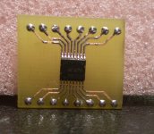
After total of 5 tries I got it down very well and the second board came out perfect!!!
It was much easier than I had expected considering that it is the smaller TSSOP SMT package and that I had hand soldered the pins.
I used Radio Shacks 62/36/2 .022 Dia. solder (Cat. 64-013) and their Non-Spill Paste rosin flux (Cat. 64-022).
I should have used the smaller diameter .015" solder for this package but it worked fine just the same.
I looked all over town to try to find some Solder-It solder paste and nobody seems to carry it any more even though I have seen it on the shelves a few years ago.
Eventually I will get some proper syringe type solder paste via mail order so that I can just use a heat gun, But these products worked just fine much to my surprise!!
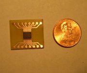
Being that this is a TSSOP-16 part it is about half the size of a SOIC-16 part and I had my doubts!!!
But not anymore !!!")
It is about the smallest there is as for as pin spacing goes, although, I know there are a few that may be even smaller but not by much!!!
I don't expect to be using anything smaller than this for the most part.
I had stayed away from this technology for many years only to find that it is much easier than I thought it would be to work with.
You need just is a little patients, lots of light and a good magnifying glass is all.
Oh,and a fine tipped iron as well.
I got a new fine tip for $2 and ground it down to suit my needs.
Once had I got my pattern save in 1200 dpi format I used IrfanView to duplicated it, as dip trace only allows you 300 pins per project.
I then printed out a whole sheet of photo paper with about 20 to 30 patterns on it in order to not waste any of the paper.
Now I have several more for other projects as it took 5 of them to make just this one (two) board !
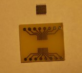
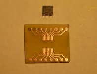
Here are some pictures of my little adapter board for the M74HC4094TTR 16-TSSOP serial in/parallel out shift registor latch that I made.
I am going to use this with a TLC548 8 bit A/D that is in a 8 pin DIP that I have had for years but never used.
Cheers !!!
jer
I just took my First plunge into the world of SMT today so I thought that I would share it with all of you as well.
This is a board that I made using DIP Trace and my Samsung ML-1865W laser pinter at a 1200dpi setting for the graphics.
I also used HP double sided photo paper.
It it took 5 tries to get the print transfer process to come out properly.
The First board came out a bit smudged with ragged edges and was not suitable for use for fear of solder bridging some of the traces.
So I used that as my practice soldering board.
After total of 5 tries I got it down very well and the second board came out perfect!!!
It was much easier than I had expected considering that it is the smaller TSSOP SMT package and that I had hand soldered the pins.
I used Radio Shacks 62/36/2 .022 Dia. solder (Cat. 64-013) and their Non-Spill Paste rosin flux (Cat. 64-022).
I should have used the smaller diameter .015" solder for this package but it worked fine just the same.
I looked all over town to try to find some Solder-It solder paste and nobody seems to carry it any more even though I have seen it on the shelves a few years ago.
Eventually I will get some proper syringe type solder paste via mail order so that I can just use a heat gun, But these products worked just fine much to my surprise!!
Being that this is a TSSOP-16 part it is about half the size of a SOIC-16 part and I had my doubts!!!
But not anymore !!!
It is about the smallest there is as for as pin spacing goes, although, I know there are a few that may be even smaller but not by much!!!
I don't expect to be using anything smaller than this for the most part.
I had stayed away from this technology for many years only to find that it is much easier than I thought it would be to work with.
You need just is a little patients, lots of light and a good magnifying glass is all.
Oh,and a fine tipped iron as well.
I got a new fine tip for $2 and ground it down to suit my needs.
Once had I got my pattern save in 1200 dpi format I used IrfanView to duplicated it, as dip trace only allows you 300 pins per project.
I then printed out a whole sheet of photo paper with about 20 to 30 patterns on it in order to not waste any of the paper.
Now I have several more for other projects as it took 5 of them to make just this one (two) board !
Here are some pictures of my little adapter board for the M74HC4094TTR 16-TSSOP serial in/parallel out shift registor latch that I made.
I am going to use this with a TLC548 8 bit A/D that is in a 8 pin DIP that I have had for years but never used.
Cheers !!!
jer
Attachments
Last edited:
Pin pitches are quite common at 0.5mm these days, there are some 0.4mm QFNs appearing. BGA's are also appearing with pitches of 0.5/0.4mm and smaller ones are being developed. This makes routing boards quite a challenge and when dealing with this size of components will use microvias and HDI PCB design
I just found this cool video of how to make a SMT Solder Paste Mask out of a aluminium pop can!!
But the coolest part was that he used some cheap Vinyl Cabinet Covering for the toner transfer process.
Has anybody tried this rather than using photopaper?!!!
DIY home-made SMT metal stencil - the definitive tutorial - YouTube
jer
But the coolest part was that he used some cheap Vinyl Cabinet Covering for the toner transfer process.
Has anybody tried this rather than using photopaper?!!!
DIY home-made SMT metal stencil - the definitive tutorial - YouTube
jer
- Status
- This old topic is closed. If you want to reopen this topic, contact a moderator using the "Report Post" button.
- Home
- Design & Build
- Construction Tips
- SMD soldering.