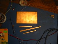
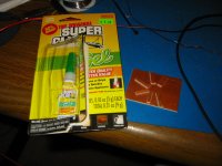
First of all I have to mention that this technique involves a certain amount of risk of getting shocked because it involves exposed electrical connections. This technique is somewhat advanced and should not be undertaked by beginers. This is a way I use to quickly prototype a tube circut in the early stages of proving it out. I cut some double sided copper clad PCB material into thin strips about 1/8" wide and mabe 1/2" long and glue them down on another piece of the same material with super glue. This provides insulated "islands" that then can be soldered to. Tube sockets and other componets can be mounted and interconnected and a circut built up.
Attachments
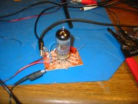
See here the assembled board under test. It took one sitting to build a working circut and provides a way to change parts and values on the fly. Also it should be mentioned that this is no way to build a perminate circut! Don't try to build a finished product this way, as the glue has a strong tendancy to break lose and voltages can end up in the wrong place 
I would like to hear opnions and perhaps others suggestions for techniques to achieve the same goal.
I would like to hear opnions and perhaps others suggestions for techniques to achieve the same goal.
Attachments
Cool.
I had a customer who needed a male connector for an old amplifier - so he made one. Carved a connector body from a piece of maple, then glued in metal pins and so on. Worked fine. I was impressed by the effort and thought he put into a simple connector. Myself I would have just bought one.
I think your little board is clever. But there are commercial product of similar nature. Antique Electronic Supply sells a variety of terminal boards with tube sockets mounted. They come in 9-pin, octal, and even a 4-pin. The boards have one, two, or three sockets. Each board has two or three rows of turret pins to solder parts to.
SOme examples
one 9-pin with three rows, stock #P-TB9-1-3
http://www.tubesandmore.com/cemirror/inv/P-TB9-1-3.GIF
two 9-pin with two rows
http://www.tubesandmore.com/cemirror/inv/P-TB9-2-2.GIF
dual octal
http://www.tubesandmore.com/cemirror/inv/P-TB8-2-2.GIF
And a couple designed specifically for old Dynaco circuits.
And for octal tubes there are things sold as "relay sockets" that are basically a plastic block with an octal socket, then a row of srew terminals along the side - one per pin.
AES sells those too, but relay sockets are also sold throgh parts houses like Mouser
http://www.tubesandmore.com/cemirror/inv/P-ST8-108S.GIF
- Status
- This old topic is closed. If you want to reopen this topic, contact a moderator using the "Report Post" button.