Quoted from the email which i sent you today, might be useful for others too till i get the manual ready:
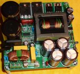
the size of the power supply board is 264x140mm and the height is about 55 mm.
the output voltage for the current version is not adjustable, it is proportional with input voltage, +-5-10%.
the caps from the secondary side are low ESR long life electrolytics, chosen depending on the working voltage and required minimum capacitance. there are 8 capacitors for the first tier rails and another 6 caps for the second tier rails.
the output usable power in audio applications, with a crest factor of 3 or more is 3600W, for continuous operation, the maximum continuous power is about 3 times smaller. the average efficiency is around 90%, with peak efficiency of 92.5% at 40% load, for the 230V version, 2x80V output and 2x120V output. switching frequency is fixed, around 100KHz.
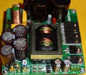
The rectifier bridge of the SMPS3K6 is rated at 50A and can withstand the average and peak current required by the power supply. please note that this power supply is intended for audio applications where the crest factor (peak to average ratio) is at least 3. The average power consumed by an audio amplifier is at most 1/3 of its rated output power, so the power supply can be thermally designed to withstand 1/3 of this power but electrically able to sustain the nominal and maximum power. in other words, with a bigger heatsink and forced air cooling should be able to deliver the rated power. I used a E55 transformer on the current boards and on the earlier prototype ETD54. any of them can sustain the required power. Double stacked EE65 cores are only required if the output power is huge, around 6-10KW or the switching frequency is very low, 20-30KHz. i also use 6x2200uF capacitors, so in total 13200 uF as can be seen in the picture.
Last edited:
Power supply(s) for 300W LME49810 Audio Amplifier?
Hi Cristi,
if I wanted to power 2 of your 300W LME49810 Audio Amplifier modules with switched power supplies all integrated into a single case. Which of your power supplies do you recommend?
As far as I understand the manual you need +/- 61V for the power stage and +/- 67V for the driver stage.
Can you potentially share a single PSU for the driver stages and get seperate ones for the power stage of each channel?
Cheers
Thomas
The most suitable power supply for the LME amplifiers, which can deliver the auxilliary voltage as well and has enogh power is the SMPS500R. the auxilliary voltage can be set to a slightly higher value than the main voltage. for each amplifier module one power supply is required, so for a stereo amp, 2 amplifier modules and 2 power supplies are required.
Thank you for the quick response. So which model of the SMPS500R would I actually need. I worked my way through all the manuals on your WEB site and I was under the impression that the SMPS5000R is a single symmetric voltage supply with an aux voltage of 5V, 10V, or 15V.
How do I get the +/- 67V for the driver stage?
Would I simply feed the same voltage to both driver and power stage and order two SMPS500R72V?
Cheers
Thomas
How do I get the +/- 67V for the driver stage?
Would I simply feed the same voltage to both driver and power stage and order two SMPS500R72V?
Cheers
Thomas
Last edited:
The auxilliary voltage or the SMPS500R is not regulated, thus can take several values, from +-12V up to about +-70V the exact value of this voltage depends on the auxilliary winding turns ratio, and should be multiple of volt/turns or in special cases multiple of half volt/turns + 1 for example if the main output is +-60V then the aux can be +-60V, +-65V or +-70V.
the SMPS500RS auxilliary voltage is regulated by a 78xx series linear regulator.
don't forget to mention the value of the voltages which you need when you place the order, and please consider that the transformer must be custom made, no additional charge, but it takes about one week more than the standard ones.
this is the SMPS500RS Connexelectronic
just leave a note about the voltages which you need and will be configured for that voltages. anyway now i should recognize your name from when you place the order.
just leave a note about the voltages which you need and will be configured for that voltages. anyway now i should recognize your name from when you place the order.
Cristi,
Among your 500W output SMPS, there are four choices:
1) A500SMPS
2) C500SMPS
3) SMPS500QR
4) SMPS500R
May you give a short briefing to customer about the difference for application:
For both Main and Aux. outputs:
1) Regulated or Unregulated
2) Voltage output: Norminal + tolerance(%)
3) Current output (Max)
The power supplies are named representing their power rating (available power for audio power amplifiers) and topologies.
A500SMPS - first generation, quasi-resonant SMPS, unregulated output voltage, no aux. output voltage
C500SMPS - first generation push-pull 12V to +-xx V power supplies, used for car audio amplifiers auxilliary regulated voltage, +-5V or +-12V or +-15V
SMPS500QR - second generation quasi-resonant SMPS, unregulated, has several improvements over A500SMPS, unregulated auxilliary voltage, proportional to the main output voltage, in range of +-5V to +-50V, with values multiples of volt/turns value, ussually 4-5V and max. current 500mA.
SMPS500R - LLC resonant topology, regulated output voltage, low ripple, both hi-freq and lo-freq ripple, have auxilliary voltage, quasi-regulated, with values in range of +-5V to +-50V, with values multiples of volt/turns value, ussually 4-5V and max. current 500mA.
SMPS800R, SMPS2000R - LLC resonant topology, regulated output voltage, regulated differential auxilliary voltage, +-5V or +-12V or +-15V.
SMPS500RS - LLC resonant topology, regulated output voltage plus one regulated auxilliary, 5V, 12V or 15V.
SMPS300R - LLC resoant, regulated single or dual output, differential auxilliary voltage.
SMPS180QR and SMPS250QR - quasi resonant flyback topology, regulated output voltage, plus one aux. voltage, 5V, 12V or 15V.
for all the power supplies the max. current of the main output depends on the power rating so Imax = P/Vout. the aux. voltage can supply 500mA, and max. 1A for short time. although it uses LM78xx regulators which are capable to deliver 1A, i sugest to not load the aux. with more than 500mA, because the heatsink temperature will increase.
Thomas,
i recommend the SMPS800R instead of SMPS500QR, it has more output power and regulated output voltage. All the quasi-resonant power supplies except the SMPS250QR and SMPS180R output voltge have larger mains frequency ripple than the regulated ones, as a coarse comparision, they are electronic transformers, with reduced weight and losses.
Need a little help hooking up the SMPS300R
Hi everyone,
I recently purchased a SMPS300R to power a Sure 2 x 100 class d amp board. I couldn't find any documentation on the Connexelectronic web site and none came with the PSU. The Sure needs a single supply and the description on the Connexelectronic web site states that it can be configured as such, but without documentation I'm at a bit of a loss on how to hook it up and adjust the output voltage. I've attached pics of the mains side and the output side of the PSU and of the power in side of the amp board. Any help would be greatly appreciated
PJN
Attachments
I'm writing the manual in the little time which i have these weeks, till then i will answer the questions regarding the power supply.
the output can be configured to deliver either dual voltage or single voltage. in case of dual voltage, there are 3 teminals, Positive out, Negative out and GND. in case of single output voltage, the Positive terminal is connected to Negative terminal, and the current capability is doubled, the rectifier diodes have the cathode connected to output. so, either positive or negative terminal can be used for positive only in single voltage mode and GND remains the same,
the mains input voltage shouls be supplied on the mains connector, the green connector from the first picture. the first terminal is protective earth, then AC voltage which can be either 230V AC (Europe and most of the world) or 120V AC (USA and Canada). for 120V a jumper must connect the pads between the two yellow capacitors. on the backside of the board is easier to connect or remove.
the small 3 pin green connector next to the two 1000uF capacitors is the auxilliary voltage output.
Hi Cristi,
Thanks for your quick reply. I can be a little dense so just to make sure that I fully understand you :
- For the single voltage output I jump the + and - outputs together and run the ground and either + or - to supply the amp board.
- For the AC supply the first terminal(the one closest to the edge of the board) is the earth.
- I have 120v so I need to jumper out the two yellow caps. By this do you mean to say to solder a wire between the two terminals on each individual cap effectively removing them from the circuit. Or do I need to solder wire jumpers from the terminals of one cap to the terminals of other cap ?
PJN
Hi Cristi,
Thanks for your quick reply. I can be a little dense so just to make sure that I fully understand you :
- For the single voltage output I jump the + and - outputs together and run the ground and either + or - to supply the amp board.
- For the AC supply the first terminal(the one closest to the edge of the board) is the earth.
- I have 120v so I need to jumper out the two yellow caps. By this do you mean to say to solder a wire between the two terminals on each individual cap effectively removing them from the circuit. Or do I need to solder wire jumpers from the terminals of one cap to the terminals of other cap ?
PJN
Hi PJN,
my advice is to be EXTREMELY careful with mods on a circuit involving deadly tensions,
and on the AC side you're dealing with 120/220 V that can kill you istantaneously.
A relative of mine died this way some ears ago.
If you shorten + and - on the DC side without additional mods you simply horten the SMPS and in the best case you can buy another one, in the worst a huge flame will burst from the transformator directly in your face.
Said that, try to get some advice from a pro (Cristi seems very occupied and I hope he will help us out with some nice scheme), here on the forum or locally. I'm not an electrical engineer and my grandfaer (who was) always told me: in doubt don't touch.
Good luck.
Hi Portomomo,
I have great reservations modifing a PSU that I know nothing about. Christi is the designer and I'll wait until I clearly understand his instructions. Some things were not totally clear to me in his last posting so I'll wait until he can clarify everything for me before I try anything.
PJN
I have great reservations modifing a PSU that I know nothing about. Christi is the designer and I'll wait until I clearly understand his instructions. Some things were not totally clear to me in his last posting so I'll wait until he can clarify everything for me before I try anything.
PJN
For the single output voltage version, the positive and negative terminals are already connected with a small jumper, either "positive out" or "negative out" can be used as positive since they are connected, and GND remains the same.
the 110V jumper pads can be seen when looking straight from above the pcb tru those yellow caps, they are separate pads, not the caps pads. only when the mains supply voltage is 100-120V they should be connected, for 220-240V they should be left unconnected.
the supply connector has the first pin connected to earth thru the small brass spacer, then the next two pins are the AC input.
i hope is clear enough, if not i will explain again. i will try to finish the manual asap and there i will explain in detail.
- Status
- This old topic is closed. If you want to reopen this topic, contact a moderator using the "Report Post" button.
- Home
- More Vendors...
- Connexelectronic
- Switched Mode Power Supplies (SMPS)