hi everyone,
I've been reading this forum for a long time but this is my first request...
I have made a half bridge class d amp not self oscillating, based on a 16MHz crystal and 4060.
the triangle wave is 700mV pp @ 250 Khz
the input opamp is TL072 (supply +-10V)
LM 319 comparator feeding a level shifter common base transistor
the next stage is 4070 and IR2113 to the N cannel Fet IRFP4227...
54uH and 470nF LC filter
post filter feedback
Power supply is +-80V 1kVA
IR2113 4070 are biased 12V over -80V
First power on no problem sound was great deep bass high frequencies clear but when i pushed it to clipping (symmetric at least !)
1 min after the 2 fet and IR2113 blow up
cooling was sufficient.
I don't know what happened please help...
Fets are not cheap and IR2113 blow every time fet do...
Hallo Alex,
the Problem seems to be the feedback. Feedback including the Outputfilter is not an easy Task, you have to deal with a 180 Deg Phase Shift.
I assume that your Amp oscillates with the Freq. of the Filter, which is approx. 30kHz using your Parts.
Pickup Feedback at the Mosfets, and don't forget to use a Zobel-Glied. Q-Factors of typical Outputfilters reach 200 and more. (Look at the GIF)
Best wishes
M.E.
Attachments
alexclaire said:hi everyone,
I've been reading this forum for a long time but this is my first request...
I have made a half bridge class d amp not self oscillating, based on a 16MHz crystal and 4060.
the triangle wave is 700mV pp @ 250 Khz
the input opamp is TL072 (supply +-10V)
LM 319 comparator feeding a level shifter common base transistor
the next stage is 4070 and IR2113 to the N cannel Fet IRFP4227...
54uH and 470nF LC filter
post filter feedback
Power supply is +-80V 1kVA
IR2113 4070 are biased 12V over -80V
First power on no problem sound was great deep bass high frequencies clear but when i pushed it to clipping (symmetric at least !)
1 min after the 2 fet and IR2113 blow up
cooling was sufficient.
I don't know what happened please help...
Fets are not cheap and IR2113 blow every time fet do...
Hi Alex,
Post your schematic first...
The problem might be in your PCB layout, Schematic design and even in the component value....
BTW:Try to increase the Bootstrap capacitor for the High side drive, your high side Mosfet might get little current to charge up during the clipping which inturn forcing it into the linear region of working and finally it damages......
regards,
K a n w a r
Did anyone knock ?? ")
Some possible sources of the problem that come to my mind:
1.) Is your switching waveform clean ( i.e. without large overshoots) ?
2.) Do you use gate series resistors (two reasons: too fast a switch-off can kill your FETs and the increased dissipation can kill your driver IC though the latter doesn't seem to be more than 1/3 of what the IC is capable to dissipate) as one should ?
3.) Is the intrinsic deadtime of this driver IC enough to prevent shoot-through ?
4.) The gate-charge of this FET isn't very high (it is actually conveniently low for such a beefy FET !) but the input CAPACITANCE definitely IS !
5.) There is no dV/dt rating on the datasheet of this FET so maybe it is not meant to be used for class-d applications.
6.) Don't drive class-d amps that are using bootstrap-capacitor-supplied high-side drivers into clipping - unless special precautions have been taken !!!!!
Regards
Charles
phase_accurate said:
6.) Don't drive class-d amps that are using bootstrap-capacitor-supplied high-side drivers into clipping - unless special precautions have been taken !!!!!
Why?
Hi alexclaire!
If your amplifier contains feedback loop, you should consider the output's delay time, what is normally 1/(2*Fs) is growing dramatically, when the FET are sticked by the clipping. This effect elongate the square signal's period time, thus divide the Fs, and multiplies the delay time. This causes insufficient stability parameters at the Nyquist criteria.
If your output filter is close to ideal. Maybe super wire, winds are far from each other, free from proximity, ideal caps... You can mitigate the filter effectively with a small serial R to the coil, or the cap. You can calculate the exact values with the transfer function.
Maybe your flying supplies at the top side are drained, and the FETs started to function as current generators, and were getting hot . One of them failed, the HV supply reached the 2113's output, and the 2113 pulled off his own hat. You should to place electrolitic caps also at the top-side supplies.
Have a nice day!
Gyula
If your amplifier contains feedback loop, you should consider the output's delay time, what is normally 1/(2*Fs) is growing dramatically, when the FET are sticked by the clipping. This effect elongate the square signal's period time, thus divide the Fs, and multiplies the delay time. This causes insufficient stability parameters at the Nyquist criteria.
If your output filter is close to ideal. Maybe super wire, winds are far from each other, free from proximity, ideal caps... You can mitigate the filter effectively with a small serial R to the coil, or the cap. You can calculate the exact values with the transfer function.
Maybe your flying supplies at the top side are drained, and the FETs started to function as current generators, and were getting hot
. One of them failed, the HV supply reached the 2113's output, and the 2113 pulled off his own hat. You should to place electrolitic caps also at the top-side supplies.Have a nice day
!Gyula
More tip: Let's consider the high-side SR Flip-Flop in the 2113. If the 2113's output ground is at a significantly lower potential than his input ground, the FF can switch on, and cause an unexpected situation.
But I think one of the FETs was taken for a ride by the flat supply, and it caused a chain reaction.
But I think one of the FETs was taken for a ride by the flat supply, and it caused a chain reaction.
phase_accurate said:Did anyone knock ??
Regards
Charles
Ahh...there we have our Charles!..... with invaluable perks for this thread
Thanks for contributing.....
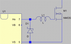
could you draw the schematic please....A photo would say 1000 words....Tim__x said:They're almost never shown, but schottky protection diodes (from the IR2113's gate output to mosfet source) are often needed. Especially with very low, or zero, gate resistors.
regards,
K a n w a r
A photo would say 1000 words....
Quite true.
Here's what I mean, D1 protects U1 from the undershoot created by the parasitic inductance L1. Without it undershoot can forward bias the substrate, in some cases causing latchup.
Attachments
What are those DO-41 diodes beside the FETs' leg? I suggest you to publish a schematic. If those are not UF rectifiers, those must be responsible for the murder. They are also pretty small for freewheeling.
I also commited to the flames a PCB three years ago. I used 1N4007 standard rectifiers for freehweeling. The supply was 100 V 50 A capable. All of the four 2113s burnt. There was about a ten centimeters tall jet of flame coming out from one of the 2113s. Half of the IC is disappeared in 2-3 seconds. The 5 mm PCB tracks between the FETs become fuses.
Your FETs have quite fast parasitic diodes, but a schematic maybe speed up the survey.
ir2113 problem
Hi,
The diodes u're talking about are anti parralel diodes over gate resistors (39 ohms) they were UF4004 but I changed them to 1N4148 advised by FREDOS (D-AMP) (4ns reverse recovery time).
Bootstrap diode was UF4004 also but not fast enough trr=50ns then replaced by MUR120 (trr=25ns) maybe the reason why it failed...
I also add 10kohms // 15V zener between gate and source of each fet in order to protect them from destructive voltages spikes...
I'm gonna try this tomorrow...
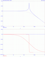
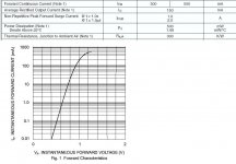
The 1N4148 is a 300 mA switch diode. It may be sufficient for simple bipolar FET controllers, but not for a 2.5 A peak output current capable driver. There is a chart and a diagram on the picture above. There you can see when the driver is switching to low, not the output resistance, but the weak diode will limit the discharging current. Then the diode's body absorbing some watts of power because of the high forvard voltage. You can see the thermal resistance in the chart (300 K/W). You can calculate the average dissipated power by the ratio of discharging and the total time. But as the body temperature rises, the chance for a thermal breakdown is getting bigger, because of the power spikes at discharging (the temperature is fluctuating at the junction).
The Non-Repetitive Peak Forward Current is Non-repetitive. This is the amount of energy the diode can absorb once started from 25C with no overheating.
There are some Schottkies with amperes forward current range, and without recovery effect, because they haven't p-n junction.
A schematic would give some help.
Attachments
- Status
- This old topic is closed. If you want to reopen this topic, contact a moderator using the "Report Post" button.
- Home
- Amplifiers
- Class D
- IR2113 blowing ! help needed...