the load that I'm planning on using this amp will be indeed 2 ohms.
the original recommended inductor value (in the daasheet) is 11uH but then jan said to wind the toroids with 26 turns so I did and measured 10.04uH. I thought "hey, it would be a shame to waste the litz wire and 1uH might not make much difference" so I stayed with it. but I still have enough to redo if necessary.
edit: do I still keep the zobel circuit and not have to change anything on that?
also, it's 2am and I need to wake up at 6am. so that means I need to get some sleep. be back tomorrow.
the original recommended inductor value (in the daasheet) is 11uH but then jan said to wind the toroids with 26 turns so I did and measured 10.04uH. I thought "hey, it would be a shame to waste the litz wire and 1uH might not make much difference"
so I stayed with it. but I still have enough to redo if necessary.edit: do I still keep the zobel circuit and not have to change anything on that?
also, it's 2am and I need to wake up at 6am. so that means I need to get some sleep. be back tomorrow.
tried the 0.47uF caps.........
with it, the output sine wave drops from 5V peak to 2V peak.
BUT! the caps heat up a bit, just warm to the touch and idle current of the amp goes way up. with the caps on both channels, my current limited supply can't provide enough current. might have to live with the higher sine wave output.
with it, the output sine wave drops from 5V peak to 2V peak.
BUT! the caps heat up a bit, just warm to the touch and idle current of the amp goes way up. with the caps on both channels, my current limited supply can't provide enough current. might have to live with the higher sine wave output.
Tekko said:That looks like a taken apart commersial amp
PERFECT boards!!!!
one is a kit from 41hz so that would explain the green PCB but the other two are made by myself. looks perfect only in the pictures.

but thanks anyway!
djQUAN said:tried the 0.47uF caps.........
with it, the output sine wave drops from 5V peak to 2V peak.
BUT! the caps heat up a bit, just warm to the touch and idle current of the amp goes way up. with the caps on both channels, my current limited supply can't provide enough current. might have to live with the higher sine wave output.
Can you draw up a schematic of the output of your amp and how everything is connected?
If the ESR of the caps you used was pretty high then the large ripple current flowing through them will cause them to heat up some. They were film caps, right?
yes, they are film caps. 200V 0.47uF which look like yellow rolled ones but oval shaped.
the slight heatsing is not much of a hassle. it's the much higher idle current that bugs me.
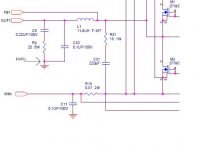
I don't have any drawing, just the schematic of the chipset in PDF file.
the PDF file is too big to attach so here is the output filter portion of the schem from the PDF.
I basically wired the 0.47uF caps across C10 in the schem on both channels.
the slight heatsing is not much of a hassle. it's the much higher idle current that bugs me.
I don't have any drawing, just the schematic of the chipset in PDF file.
the PDF file is too big to attach so here is the output filter portion of the schem from the PDF.
I basically wired the 0.47uF caps across C10 in the schem on both channels.
Attachments
Hey djQUAN
Which toroidal cores are you using for your monster power supply ?
I'm getting an amp going but with the overwhelming number of cores available and the useless sales support from electronics companies in ZA, i'd be keen to know which ones you are using.
Secondly, dont you find the diodes heat up quite a bit with the 1.9V forward drop when delivering the current ?
Regards
I have no idea what my cores are since I got them from a flea market.
but I measured their AL value to be about 5+mH/T^2 which is about on the high side and the outer dia to be around 2"
I used 6+6T for the pri and 24T for the sec.
I haven't tested the amp at full power yet since I still have to chassis to be built. I will be using the bottom plate (1/8" thick aluminum) as the SMPS heatsink.
UPDATE!!!!!!!!!!!!!!
I was able to complete 90% of amp8 yesterday and have done a little bit of torture testing.
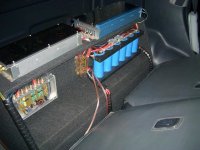
I'm not yet sure how much power I'm getting from the amp but my car's alternator and battery are starting to give up. It blew a 40A fuse like popcorn and the 60A is still holding up. though the amp cuts off some of the time due to low voltage most possibly due to the batt and alt sagging. I got a in dash voltmeter and I can see it drop to 12.4V (13.8V at no music) with the engine running at idle.
the main SMPS seems to be holding up well since the fets ,rectifier diodes and main toroids are berely getting warm.
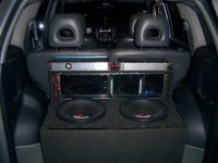
I'm guessing it's putting up some power since my subs are beginning to smell after a minute or two. they are both dual 4 ohm coil wired in series to get 8 ohms per sub then two wired parallel to get 4 ohms. then they are bridged on the two channels so the amps are basically running at 2 ohms each.
the mosfet heatsinks are running hot but are still manageable. the driver chip stays the same temp at idle or at high output, the zobel resistors get burning hot (guessing about 60-70 degrees C) and also the toroids. the toroids are getting a bit too hot for my liking so I'm thinking of rewinding them again but I'm gonna have to make my own litz wire since I don't have enough left.
I'm gonna rewire the toroids with a bit more turns to lessen the residual at the outputs since this thing is already an EMI nightmare when a drum core inductor is connected to a scope to measure EMI radiation around it.
I was able to complete 90% of amp8 yesterday and have done a little bit of torture testing.
I'm not yet sure how much power I'm getting from the amp but my car's alternator and battery are starting to give up. It blew a 40A fuse like popcorn and the 60A is still holding up. though the amp cuts off some of the time due to low voltage most possibly due to the batt and alt sagging. I got a in dash voltmeter and I can see it drop to 12.4V (13.8V at no music) with the engine running at idle.
the main SMPS seems to be holding up well since the fets ,rectifier diodes and main toroids are berely getting warm.
I'm guessing it's putting up some power since my subs are beginning to smell after a minute or two. they are both dual 4 ohm coil wired in series to get 8 ohms per sub then two wired parallel to get 4 ohms. then they are bridged on the two channels so the amps are basically running at 2 ohms each.
the mosfet heatsinks are running hot but are still manageable. the driver chip stays the same temp at idle or at high output, the zobel resistors get burning hot (guessing about 60-70 degrees C) and also the toroids. the toroids are getting a bit too hot for my liking so I'm thinking of rewinding them again but I'm gonna have to make my own litz wire since I don't have enough left.
I'm gonna rewire the toroids with a bit more turns to lessen the residual at the outputs since this thing is already an EMI nightmare when a drum core inductor is connected to a scope to measure EMI radiation around it.
- Home
- Amplifiers
- Class D
- Big-t