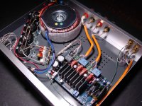
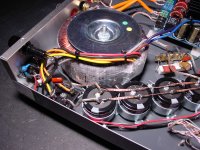
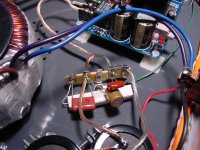
HiFimeDIY T1, pics from today...added some 27 ohm resistors to the inputs.
Attachments
Last edited:
Like the enclosures .... where to get these
Thanks Baldin
Not exact the same but pretty close.
Wholesale beautiful full aluminium pre AMP BOXchassis for DIY
freight becomes quite huge, for chassis this size.
Hi Tangmonster, how do those L15D modules sound? Thanks
I have only used them for the subwoofer (<80hz).
Haven't used them on full range.
very happy with the efficiency and simplicity. sounds great for my sub woofer use.
One thing i can say is you HAVE to use them in either bridge mode into single 8 ohm load. Or you have to drive the one out of phase with the other one.
I had MAD buss pumping when I tested them for the sub woofer with both channels in phase for high volumes
simple opamp inverter on the one channel with the output polarity switched is fine.
For lower volume it will probably be fine but not high volume low frequencies.
I had audible loud noises (sounds something like hitting a stick on the floor) when board switched off on over voltage due to the buss pumping. All disappeared once i connected them up out of phase.
Like the enclosures .... where to get these
Thanks Baldin
Couple years ago from eBay.
Don't know where to get them now,
but there are look a likes.
i'm trying to design my class d amp using ir2110 but something is going wrong....plz anybody help me out....my head is just blown out
If you want help, I think you need to move this question to the regular Class D section (not the Gallery). And we need a lot more details to be able to help: Schematic, pictures, description of what is working and what is not!
Best regards Baldin
")
2x L15D v3
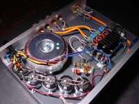
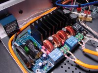
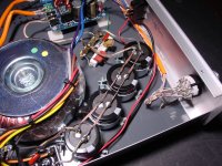
awful wiring i might say since holidays are sneaking up i had to do the wiring in a afternoon it sucks and it doesn't look safe ohh yes and it has no general color scheme its just kinda random wires going every where. i replaced all the caps on one of the amp boards and need to do it on other one, the channel with replaced caps takes about 5 seconds to turn on after the side. i didn't have any bus pumping down to 45hz this is as far as ill ever go. ohh yes i didnt end up with any ground loop thanks to the sticky thing on star grounding even though i didn't do it correctly it worked out
i was shocked it work considering i hadn't in my life ever thought of putting a outlet together not to mention a amp 8 weeks ago
An externally hosted image should be here but it was not working when we last tested it.


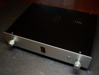
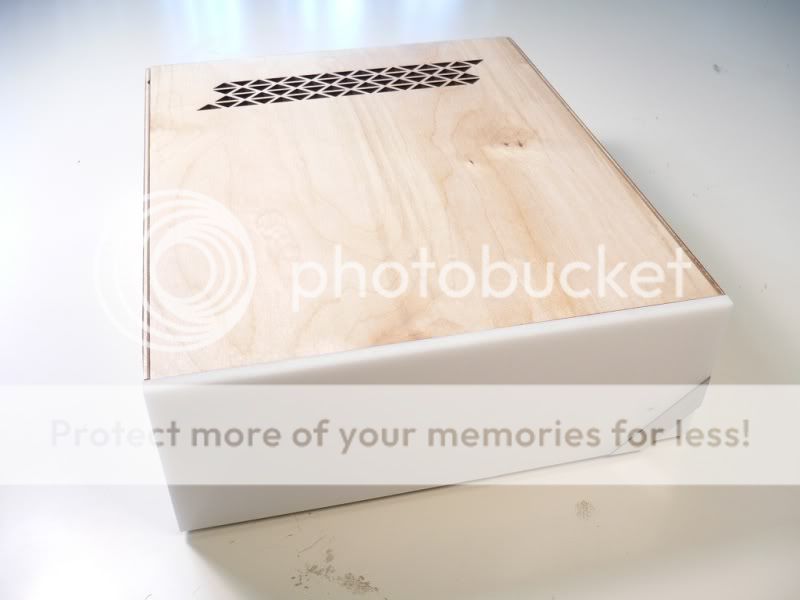
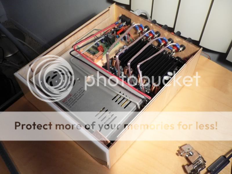
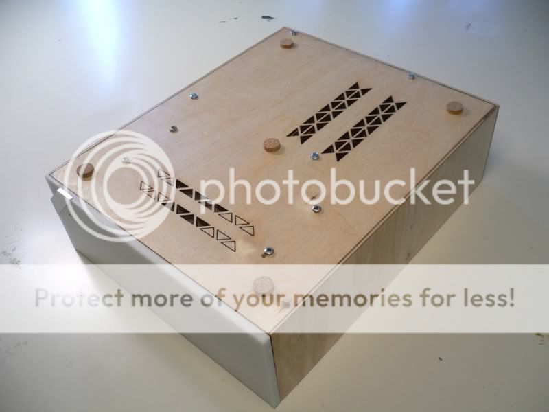
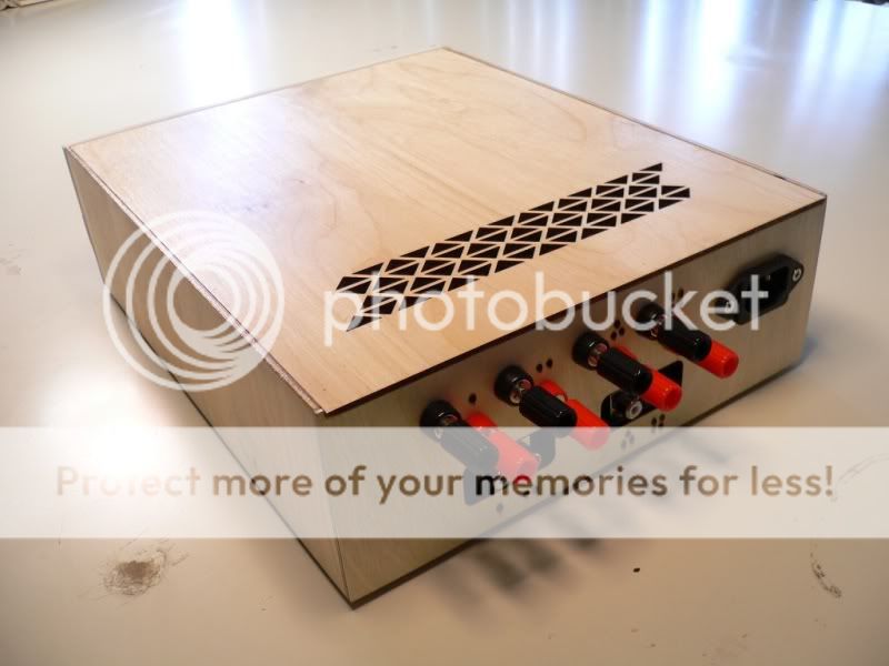
My humble entry. A mundane Sure 4 channel amp.
WOW!! That is a beautiful and original design. Congrats.
My humble entry. A mundane Sure 4 channel amp.
Nice job,
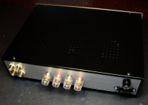
what are the extra two little boards near the power jack?
My humble entry. A mundane Sure 4 channel amp.
I love the ventilation holes.
 That looks great! How did you cut them? It looks like cut with a laser.
Hello lovro, the two boards are a touch switch (the aluminium strip on the front) to turn on the amp. Hi Joschi thank you for your comments, and yes indeed they were laser cut the funny thing is that I was in a hurry building this and I totally forgot to laser engrave the info on the back (inputs, outputs, etc) so I ended up burning in those dots by hand for indication :/
the funny thing is that I was in a hurry building this and I totally forgot to laser engrave the info on the back (inputs, outputs, etc) so I ended up burning in those dots by hand for indication :/- Home
- Amplifiers
- Class D
- Class D Amp Photo Gallery