The conversation is interesting but perhaps I get lost in translation.
For me they are two separate issues. One is the noise (pink-noise at output), this is much greater than in the BD modulation. second point is the noise (EMI radiation)...
White noise actually. But the EMI is lot more complicated because of mosfet body diode currents, power supply currents etc. Common mode rf stuff. But the white noise can go out onto the speaker line and cause emi as well but this is easy to filter. Big loops in your bridge circuit are a different matter.
do you really think, that the residual is of a sinusoidal form?
Of course not. It's the sum of infinite sinusoidal components (fourier series), and the freq of first (and dominant) component is fsw. And this component won't magically disappear if you add the two signal, because they are in phase! Don't mix addition and subtraction! If you subtract them, they cancel each other (this is one of the main goals of BD modulation). If you add them, they dont. And if there is a component at fsw, then the whole signal can't be periodical with 1/(2*fsw).
But at low modulation index both outputs are almost perfectly sinusoidal, in this state you can clearly see (without any mathematics, without spectral composition) that your statement is impossible.
Ok, I will do simulation and I will post result here
Do it, and you will see!
I simulated both AD and BD modulations, and found, that BD modulation indeed does not doubles the radiated frequency... My bad 
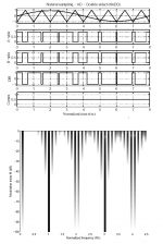
But it have proven the Bruno's sentences about cancelling of the radiated ripple in common mode in BTL configuration with AD modulation. Please, see attached images. Red trace is what will be radiated off cables. Each output wire will radiate its own ripple voltage and it will be summed in the air then. And since in BTL configuration with AD modualtion the residual ripple is in opposite in output wires, radiation will be cancelled (but on the speaker it will be doubled).
But it have proven the Bruno's sentences about cancelling of the radiated ripple in common mode in BTL configuration with AD modulation. Please, see attached images. Red trace is what will be radiated off cables. Each output wire will radiate its own ripple voltage and it will be summed in the air then. And since in BTL configuration with AD modualtion the residual ripple is in opposite in output wires, radiation will be cancelled (but on the speaker it will be doubled).
Attachments
Last edited:
White noise actually. But the EMI is lot more complicated because of mosfet body diode currents, power supply currents etc. Common mode rf stuff. But the white noise can go out onto the speaker line and cause emi as well but this is easy to filter. Big loops in your bridge circuit are a different matter.
yes white-noise, sorry I said pink only for said "his" noise at output.
this is not possible eliminate with filter,. fb,circuit, and pcb design.
I agree with PAFI,carrier not sum. Remaining (for me) double EMI and linearity of modulation on BD. I tested bd modulator hw, it have IMD on signal output, it tested on identical trw for AD modulation.(300KHz)
Regards
bas81!
Thanks for doing sims, and admitting the result!
Yes, balanced AD doesn't have common mode output component, and BD does, that's obvious, but my point was: this is not that important as you may think. I don't know anybody who wants to listen to AM radio near to a big PWM amplifier, but if you want, you can suppress common mode component by 60 dB easily, with about 4 dollars cost.
AP2, ericbrookling!
I don't know what noise could you talk about... In a theoretical PWM modulator there is absolutely no audio-band noise. Noise comes from not perfect elements (comparator, etc). There is some disturbance at high modulation index and high modulation frequency, but it's not noise, it's side-band leakage, the same as in FM or PM modulation. Its spectra is not continuous like white noise, but discrete, related to modulating signal.
What is "trw"?
An ideal 150 kHz BD modulator has a bigger distortion then a 300 kHz AD, that's true, but generally both are much smaller then the distortion of the power stage.
I don't know what noise could you talk about... In a theoretical PWM modulator there is absolutely no audio-band noise. Noise comes from not perfect elements (comparator, etc). There is some disturbance at high modulation index and high modulation frequency, but it's not noise, it's side-band leakage, the same as in FM or PM modulation. Its spectra is not continuous like white noise, but discrete, related to modulating signal.
I tested bd modulator hw, it have IMD on signal output, it tested on identical trw for AD modulation.(300KHz)
What is "trw"?
An ideal 150 kHz BD modulator has a bigger distortion then a 300 kHz AD, that's true, but generally both are much smaller then the distortion of the power stage.
Last edited:
Kanwar asked about the reverse recovery problem.
In a full-bridge BD topology the reverse-recovery issues would be the same as with a full-bridge AD or a half-bridge. So no advantage in this respect.
Do you still use the topology that you once told me about and that does reduce the reverse recovery problem ?
Regards
Charles
In a full-bridge BD topology the reverse-recovery issues would be the same as with a full-bridge AD or a half-bridge. So no advantage in this respect.
Do you still use the topology that you once told me about and that does reduce the reverse recovery problem ?
Regards
Charles
Kanwar asked about the reverse recovery problem.
In a full-bridge BD topology the reverse-recovery issues would be the same as with a full-bridge AD or a half-bridge. So no advantage in this respect.
Do you still use the topology that you once told me about and that does reduce the reverse recovery problem ?
Regards
Charles
Thanxz Charles
")
Yeah i still have that cascode switching topology in some modules under production and it eliminates the reverse recovery problem completely.
The main issue in Half-Bridge is bus-pumping[with +/-180V the rails pumps to 230V under severe LF signal conditions] which is making me to use bridged versions more likely.
Regards,
Kanwar
AP2, ericbrookling!
What is "trw"?
An ideal 150 kHz BD modulator has a bigger distortion then a 300 kHz AD, that's true, but generally both are much smaller then the distortion of the power stage.
Hi,
"TRW" is triangle wave, ok thank for your reply.
I was looking for the best way to make a new class D amplifier and I am of the opinion that some innovations on AD are the best you can get.
example I try double comparators (just out of phase) on AD modulator and saw that cancel "lish" and noise. BD did not get anything better.
Regards
AP2, ericbrookling!
I don't know what noise could you talk about... In a theoretical PWM modulator there is absolutely no audio-band noise. ...
The "noise I'm talking about is out of band. It's just the difference between the PWM output and the intended pure audio. Several papers have modelled this as a uniform noise added to the audio. This is not the normal way to look at PWM, but this "noise" is the carrier with modulated signal and it's harmonics. Forget I mentioned the whole thing, from now on I'll only speak of this in modulation terms. Thanks.
AP2!
A BD modulator is two AD modulator + an inverting amplifier. If the triangle is identical, and inverter is perfect, then BD modulator can't have more distortion then an AD modulator! Distorted components of AD plus distorted components of inverted AD is equal or less 2*distorted comp of an AD. Output of BD is the sum of a simple and an inversely modulated AD. So D(BD)<=(D(AD)+D(inv.AD))/2. Since a good modulator is symmetrical, D(AD)=D(inv.AD), D(BD)<=D(AD).
If you found something else, then you measured something else than the modulator itself.
I don't understand. What was out of phase? The second comparator? Then it's still AD. What happend? What does "and saw that cancel "lish" and noise" means?
BD in itself doesn't help, thats true, but it makes the possibility to make improvements (stronger feedback, smaller filter, or lower fsw->higher efficiency, etc...). So direct comparison without optimization is a waste of time.
I tested bd modulator hw, it have IMD on signal output, it tested on identical trw for AD modulation.(300KHz)
A BD modulator is two AD modulator + an inverting amplifier. If the triangle is identical, and inverter is perfect, then BD modulator can't have more distortion then an AD modulator! Distorted components of AD plus distorted components of inverted AD is equal or less 2*distorted comp of an AD. Output of BD is the sum of a simple and an inversely modulated AD. So D(BD)<=(D(AD)+D(inv.AD))/2. Since a good modulator is symmetrical, D(AD)=D(inv.AD), D(BD)<=D(AD).
If you found something else, then you measured something else than the modulator itself.
example I try double comparators (just out of phase) on AD modulator and saw that cancel "lish" and noise. BD did not get anything better.
I don't understand. What was out of phase? The second comparator? Then it's still AD. What happend? What does "and saw that cancel "lish" and noise" means?
BD did not get anything better.
BD in itself doesn't help, thats true, but it makes the possibility to make improvements (stronger feedback, smaller filter, or lower fsw->higher efficiency, etc...). So direct comparison without optimization is a waste of time.
Last edited:
HI,
TO ericbrookling,Pafi.
You said well, I was referring precisely to this noise, is given by the components (harmonics) generated by TRW. FFT is very full (even feel the bass). can greatly help the feedback and the TRW-PCB design. it is obvious that other circuits are responsible for up to mosfet
PAFI>
yes
know well the theory but the reality is unfortunately not as you say.
if you drive two comparators with the same TRW but reversed phase , errors will be mirrored. My testing on BD shows it , increased IMD (intermodulation distortion) not thd at 1KHz. obviously more modular frequency signals on different shows more irregular (PWM Linearity and delay). BD is not the right way to solve the problems of class D (IMHO).
----------------------------
I'm trying a modulator (parallel comparison). TRW driving one specific stage 4 comp. out under progressive small delay, with this configuration eliminates "glish" on the PWM (product conversion is clean). see what I gained with other tests.
know well the theory but the reality is unfortunately not as you say.
I believe you, but if practice is different in your specific case, then the experienced error comes from the realisation. And this error is not unavoidable. (However it can be a challange. I also experienced extra distortion at BD, but in my case it came from unintended feedback of switching transient to modulator. I couldn't eliminate it completely, but I'm on it. 4 layer PCB would help a lot, but it's too expensive, so I try to modify the main feedback loop instead.)
errors will be mirrored.
Yes, and because signal is differential, the errors are summed (not exactly, because some error components may hold their polarity). But signal is mirrored too, the resulted amplitude is double. This way the distortion/signal ratio can be smaller or equal to the one of an AD modulator.
Someone who I am currently helping to design the feedback loop of a class-d amp mentioned a paper by Lars Risbo where he came to the conclusion that bridged BD would offer the lowest distortion of all half and full-bridge topologies. I can ask him for the title of the paper.
But the one I am talking of was insisting on a bridged BD from the beginning. It is quite interesting that he achieved k3 of about 0.1 % with the very first incarnation of his PCB after some slight modifications of the feedback loop and the output filter. IMO this is not audiophile performance but it is indeed very good for a first try.
I will open a thread for the feedback topology he is using - as soon as I know whether I can simply post the underlying paper here or if I'd have to do changes to it (due to copyright reasons).
Regards
Charles
Last edited:
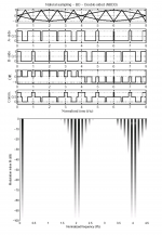
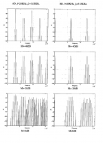
BD & AD Modulation
Cool pictures!
Could you please build these black&white 'hystograms' for common mode voltages too?
Many thanks!
Cool pictures!
Could you please build these black&white 'hystograms' for common mode voltages too?
Many thanks!
I think common mode voltages are already represented graphically inthat post.
I think common mode voltages are already represented graphically inthat post.
I meant to build these vertical bar-graphs for common mode voltages... Really don't know, how they are called, 'spectra' maybe?
I meant these vertical bar-graphs... Really don't know, how they are called
Histograms
- Status
- This old topic is closed. If you want to reopen this topic, contact a moderator using the "Report Post" button.
- Home
- Amplifiers
- Class D
- AD Vs BD Modulation in Class-D