Read my comment again: the OPT must handle the full AF spectrum. You also must filter the HF before the transformer, because one you don't need it, and two, it'll cook your transformer by eddy currents.
Berning's circuit amounts to a chopper amplifier. A square wave at 200kHz or so alternately connects an output tube (via bridge-connected MOSFETs and FWB diodes) to the output (speaker) through an HF transformer. The actual chopped waveform looks like AM with a square carrier; you could think of it as synchronous modulation/detection.
Tim
It is, in as much as the modulator itself provides the link. It isn't one-way but bidirectional. The chopper literally connects input to output.
I've chatted with David and he said he uses a large number of secondary windings and bridge rectifiers to reduce capacitance. A damper diode such as 6CL3 (PRV ~ 5kV, Ipk ~ 1A, R(effective) ~ 25 ohms IIRC) would indeed have lower voltage drop than the ~20 SS stages recommended for his 811(?) amp, but he felt that his was was more practical. Maintaining a square wave at that kind of voltage swing is a considerable challenge. I don't think it was the most efficient way to go, but that's me.
Demodulating AM cannot be done very easily with more than 25% efficiency. For example, you can take a bog standard ATX switching power supply, hack into the voltage feedback node and PWM it with audio, but you can only get that audio back off the outputs if you capacitor-couple it, and since the capacitors would charge completely via the diodes, a constant load current must be supplied to provide down swing on that output. Therefore, the output network (LPF, load resistor and coupling capacitor) is "class A", attaining a theoretical maximum of 25% efficiency.
Sch3mat1c said:
I've chatted with David and he said he uses a large number of secondary windings and bridge rectifiers to reduce capacitance. A damper diode such as 6CL3 (PRV ~ 5kV, Ipk ~ 1A, R(effective) ~ 25 ohms IIRC) would indeed have lower voltage drop than the ~20 SS stages recommended for his 811(?) amp, but he felt that his was was more practical.
But he needs masses of these SS rectifiers. What is practical about that? And don´t they pollute the harmonic spectrum? From my understanding this should sound like just another hybrid amp, but there are too many people who say it doesn´t.
Sch3mat1c said:
Demodulating AM cannot be done very easily with more than 25% efficiency. For example, you can take a bog standard ATX switching power supply, hack into the voltage feedback node and PWM it with audio, but you can only get that audio back off the outputs if you capacitor-couple it, and since the capacitors would charge completely via the diodes, a constant load current must be supplied to provide down swing on that output. Therefore, the output network (LPF, load resistor and coupling capacitor) is "class A", attaining a theoretical maximum of 25% efficiency.
And when I don´t need coupling, e.g. for driving an ESL?
Sch3mat1c said:You also must filter the HF before the transformer, because one you don't need it, and two, it'll cook your transformer by eddy currents.
Hi, at my simulation, current through U2 is about 0.065A, and voltage difference is 30V, so about 2W is consumed at transformer. (speaker output is also 2W range. 50% efficiency)
I'm not sure 2W will cook transformer. (not good at DIY tube amps)
Sorry for the thread necro 15 years after.. but did you get any further with this?
Simply put I'm looking at ways (perhaps intellectual boredom) to increase current delivery and drop output impedance for OTL amps beyond simply adding a mosfet follower.
So I have PWM servo experience, an understanding of SMPS (I'm building my own 48V->200-500V booster and have looked into most of the options). I've also modified Marcel's ValveDAC for different tubes, so my thinking here is I would add a DSD512 stream into the mix at some point. I looked at magnetic amps as a way of controlling - this allows an AC load with an AC input to be controlled through a DC winding, although a square wave wouldn't work well, a triangle wave may just work nicely..
An alternative is a tube SMPS which smokingamp graciously provided a schematic for - great for voltage but lacks that current punch without some adjustment to the SMPS transformer to convert to current.
Ideally I was thinking tube modulated SMPS, or at least power controlled directly connecting isolated DC power of 48V to low as 1.2V. It's occurred to me that the PWM chopping I've done previously (12V supply into a 3.2V servo) provides the same back EMF capability. In the end it comes down to a chopper/switching and this just so happens to basically be the same as a class D so a search popped up with this thread.
So.. did anyone try building this?
Hi, I am new here. I came in after search for class D amps, using RF tubes.
Many points have been made here, showing design obstacles.
My one: First of all, I have experience with tubes, switch mode power supplies, DC motor servo drives with slow, high energy transistors, RF designs.
I think about linking a set of EC70 ferroxcube cores, working at ~ 0.5 MHz PWM, I want the amp capable to cover 20 to 20.000 Hz with full power, I want a feedback loop over the power stage, at least until 10 kHz in order to get lowest distortion.
My tubes are not finally selected, but I have QQE06/40 as my favourites.
Is there anybody here, who has finally finished a project with RF tubes for audio output, without using a 'standard' push pull LF transformer?
Greetings, Joachim
??????????There is no way to push audio-band power over your ferrite cores, no matter if continuous audio or chopped with pwm. Period.
Joachim is talking:
class D amps ..... EC70 ferroxcube cores, working at ~ 0.5 MHz PWM
I find that impractical, but definitely possible.
Just want to clarify: Any PWM signal, based on RF, will drive a small core into saturation, if it is
1. Non-symmetric for extended periods, which is the case in my idea
2. If the magnetic energy stored extends the capacity of the core.
The purpose of the RF based design is, to avoid the very bad transfer function of iron cores for higher audio frequencies.
Second purpose is, to allow a significant feedback, meaning high amplification and differential processing in a PID element.
All depends on the amount of ferroxcube, with low parasitics in the windings.
There is no way to push audio-band power over your ferrite cores, no matter if continuous audio or chopped with pwm. Period.
I worked with large ferroxcube cores for quite a while. It depends on how you put energy in and move it out to sink side. Remember: if you were right, DC would be impossible, too. But 0 Hz is easily achieved, with feedback loop and very, very tiny cores.
I do not state: PWM of one single, fixed base frequency is the only possible way to put energy in. Rethink, what coils on RF make different from coils on AF.
I do not couple an H bridge to a plain transformer.
My understanding was you want to replace the bulky iron xformer by some smarter ferrite cores by using pwm - a common misunderstanding - which will not work.I worked with large ferroxcube cores for quite a while. It depends on how you put energy in and move it out to sink side. Remember: if you were right, DC would be impossible, too. But 0 Hz is easily achieved, with feedback loop and very, very tiny cores.
I do not state: PWM of one single, fixed base frequency is the only possible way to put energy in. Rethink, what coils on RF make different from coils on AF.
I do not couple an H bridge to a plain transformer.
output stage
Hi,
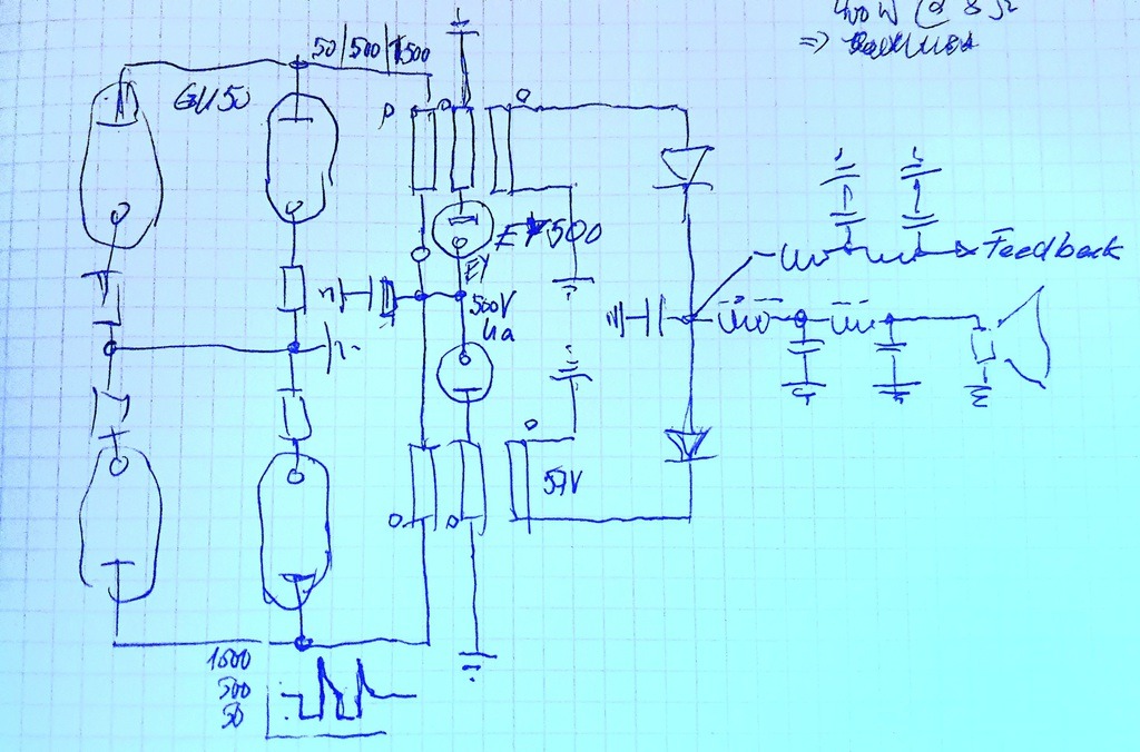
I had a rough idea and made a sketch, omitting anything which is not important for now. Meaning, I focused on the ferroxcube drive and the method to discharge the magnetic energy.
Please note, it is not yet decided to use the GU50. The use of EY500 is just a matter of beauty. It's purpose is, to let the extra (middle) winding pull out that energy from the core, while driven with ~500V main anode voltage, that winding is ~ one third the primary winding count. Voltage will rise the anode to up to 1500V in a very secure 'off' phase, g1 might get more then 50V negative bias. So that is safe. Advantage: energy is pulled out in about a third of the on-time of the tubes.
Overall, it is a Push-Pull and the tubes are switched between ~300mA each and ~0mA, the AF frequency will modulate the on-phase length. I omitted the generation of gate voltages and the feedback loop. Without the feedback loop, the entire thing will not do anything. With it, I expect a very, very low output impedance and low distortion up to several kHz.
The output coils will be designed for 500 to 57 Volts, roughly.
This output stage must be operated within a very good RF cage, because it will produce enough RF to be reflected by the moon. But I have experience with such effects and have equipment, to measure and suppress as much as possible.
The 3 windings will reside on a double EC70 core, something I can easily get and which is well documented.
If you do not have experience with fast switching: This is not comparable with a class AB. No tube will have a chance, to run in fully opened state until transformer saturation. This will be ensured by the driving circuit, which also contains the feedback loop. The magnetic energy in the core is very low! Coupling of windings is transferring the pulses energy, which are formed to AF in the output filter. That one gets high current, but only needs low inductance.
The capacitor after output diodes will be a set of high quality ceramic or foil caps. Output diodes must withstand 120V, high current. That's easy to get.
The EY500 allows 500mA max and will be fast enough. It puts the magnetic discharge back into the 500V supply.
Anode current will reach up to 600mA total, but due to relaxation in the opposite AF swing and the maximum 66/33 duty cycle, the 4 tubes will survive and not overheat or exceed parameters.
The diodes at the output might need some additional assistance for performance reasons. But for now, this is a starting point.
Efficiency is out of discussion, I like tubes, that's it. One single circuit implementation and then, enjoy the infrared light show .
Greetings from a crazy designer ,
,
Joachim
Hi,
I had a rough idea and made a sketch, omitting anything which is not important for now. Meaning, I focused on the ferroxcube drive and the method to discharge the magnetic energy.
Please note, it is not yet decided to use the GU50. The use of EY500 is just a matter of beauty. It's purpose is, to let the extra (middle) winding pull out that energy from the core, while driven with ~500V main anode voltage, that winding is ~ one third the primary winding count. Voltage will rise the anode to up to 1500V in a very secure 'off' phase, g1 might get more then 50V negative bias. So that is safe. Advantage: energy is pulled out in about a third of the on-time of the tubes.
Overall, it is a Push-Pull and the tubes are switched between ~300mA each and ~0mA, the AF frequency will modulate the on-phase length. I omitted the generation of gate voltages and the feedback loop. Without the feedback loop, the entire thing will not do anything. With it, I expect a very, very low output impedance and low distortion up to several kHz.
The output coils will be designed for 500 to 57 Volts, roughly.
This output stage must be operated within a very good RF cage, because it will produce enough RF to be reflected by the moon. But I have experience with such effects and have equipment, to measure and suppress as much as possible.
The 3 windings will reside on a double EC70 core, something I can easily get and which is well documented.
If you do not have experience with fast switching: This is not comparable with a class AB. No tube will have a chance, to run in fully opened state until transformer saturation. This will be ensured by the driving circuit, which also contains the feedback loop. The magnetic energy in the core is very low! Coupling of windings is transferring the pulses energy, which are formed to AF in the output filter. That one gets high current, but only needs low inductance.
The capacitor after output diodes will be a set of high quality ceramic or foil caps. Output diodes must withstand 120V, high current. That's easy to get.
The EY500 allows 500mA max and will be fast enough. It puts the magnetic discharge back into the 500V supply.
Anode current will reach up to 600mA total, but due to relaxation in the opposite AF swing and the maximum 66/33 duty cycle, the 4 tubes will survive and not overheat or exceed parameters.
The diodes at the output might need some additional assistance for performance reasons. But for now, this is a starting point.
Efficiency is out of discussion, I like tubes, that's it. One single circuit implementation and then, enjoy the infrared light show .
Greetings from a crazy designer
,Joachim
Hi again,
In the meantime, I ordered some central components, in order to check the switching output stage. So a set of toroid power transformers along with the ferroxcube cores, 600V caps, different NTCs for enabling the .5kW toroid to be switched on without blowing my fuses and switches.
Power will be transformed from 230V AC to 12 + 12, from 24 back to a set of 115V AC, which will add up to roughly 500V DC.
I decided to make that DC voltage with remaining ripple.
Why?
I want to use that ripple as a test for the feedback loop.
Did I mention, that upper concept is capable, but I do not want to make use of it, to generate DC. The lowest frequencies will be cut off.
Primary target with first component assembly is, to verify the power capability of the key components. Then, I will tune the output filters to reach 20 kHz and get a smooth sine of it.
I also ordered a larger set of noval PCC89 RF (UHF) tubes, double triodes for the gate driving of the output stage.
The lower cathodes will be supplied from about -100V DC (regulated). The upper triode anodes from another 100V DC (regulated).
These voltages are taken from 115V windings mentioned above.
Those triodes can be used in the feedback loop, too. But that path will contain semiconductors for signal processing, probably. At least, when I start the design.
But there are quite good proposals for opamps, using tubes.
The heating voltages are taken from the 12 + 12 V intermediate power train. Any load misbalances, which will occur, will not lead to problems, because of the tight coupling in toroid windings.
The output transformers will be made by myself, with material I have in stock.
That will be a bit of thrill, to make all those high voltage measurements. 1500V with lots of power at the GU50 and 500 DC anode main power.
Greetings,
Joachim
- Home
- Amplifiers
- Class D
- tubes in Class D?