I found it easy to solder a 1200uf 16V Panasonic FC cap directly at power pins of SI chip and still use the regular case - just solder pos lead of cap to smd caps(there are two which connect through a via to the power pins) on bottom of board and neg cap lead to solder heatsink which is spread all around chip.
By mounting this cap on its side it is low enough to fit in the standard case!
This positioning givesd as close a position to SI power pins as is possible and probably leads to lower inductance, etc as is possible - no bas thing ala chipamp forum
John
By mounting this cap on its side it is low enough to fit in the standard case!
This positioning givesd as close a position to SI power pins as is possible and probably leads to lower inductance, etc as is possible - no bas thing ala chipamp forum
John
Complete noob here. Do you guys have any pics and places to buy cases? Do you also have pics on how to replace the most easily replaceable parts. I read that some of the caps can be pulled out and new ones just snapped in place. Did I read that correctly?
I will be using Athena AS-B1 90db 8ohm speakers in a 10x12 bedroom.
Thanks for all the help.
I will be using Athena AS-B1 90db 8ohm speakers in a 10x12 bedroom.
Thanks for all the help.
There's 3 types of cases I've seen used for these if you don't want to roll your own.
1) Hammond Aluminum 1455 series case: http://www.hammondmfg.com/1455.htm (these are available at most of the major electronics distributors: digikey, mouser and parts-express)
2) Par-metal: http://www.par-metal.com/ (most folks use the 20-xxxxx series cases)
3) Context Engineering: http://www.contextengineering.com/ (available locally at the Fry's Electronics in my area).
I'm sure there are others, but these are the main three I'm familiar with. If you poke around the in the other SI threads, you'll find folks have posted pictures and/or answers to your other questions.
Some of the larger par-metals probably would:
http://www.par-metal.com/plist.htm
20-08125x 33.50 30.20 27.20 24.50 8W x 12D x 4.75H
You might be able to go with a smaller box, depending on how big your SLA is. Take a look at that page and see which one would suit you best.
Otherwise you might want to poke around on head-fi.com .. I think they have a list on there somewhere of about 20 different case manufacturers for DIYers.
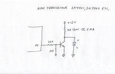
Overload LED Indicator
As per Tripath Technical information for the 2024, pin 7 (overloadB) is a 5 volt lofic output, which at low level indicates an overload in the input signal causing distortion, however, this pin can't directly drive a LED, does anyone have an idea how to implement a "buffer circuit" to drive a LED? Thanks.
As per Tripath Technical information for the 2024, pin 7 (overloadB) is a 5 volt lofic output, which at low level indicates an overload in the input signal causing distortion, however, this pin can't directly drive a LED, does anyone have an idea how to implement a "buffer circuit" to drive a LED? Thanks.
I've started my T-Amp odyssey a bit late compared to you guys. I really appreciate the path that you have blazed for the rest of us. I've decided to do some modest modifications including:
Case
Connectors
Potentiometer
Power Supply
Input Capacitors
I feel that this will not stress my modest skills with the soldering iron and still give me the most return on investment.
So far I've performed some plastic surgery (case removal), hooked it up to my Astron power supply and some Acoustech HT75 (BIC) towers (Klipsch wannnabees). My first listening experience was horrible. I played some Mozart on a portable CD player. It was so noisy I almost couldn't listen. I was very disappointed. Then the piece ended and sweet silence enveloped me......... (c8 The CD was the culprit. The sound is so good that you will hear things that have been hiding up to this point. If you use an MP3 player, be prepared to start re-encoding your music at higher bit rates!
I'm wondering if someone can answer a few questions I have regarding the replacement of the input capacitors.......
Motherone suggested bridging both C3 & C4. He also stated that he'll connect the new capacitors directly to the RCA input jacks. I assume that they are connected to the input jack traces. After looking at Panomaniac's schematic (which is somewhat different from the SI data sheet), I'm wondering if it will matter that the new input caps will be in a different position in relation to R01, C1, L1 and the Potentiometer? This certainly seems easier than trying to replace the existing SM devices, but I don't want to assume anything with my Jr. High level electronics background.
Best regards,
PCH
Input cap question
http://www.diyaudio.com/forums/showthread.php?postid=571880#post571880
In this post (#21 in this thread) there is a drawing of the input circuit. As can be seen if you jumper out c3, c4 you will be connecting r01, r02 directly to the input. This causes a DC offset and will shut the chip down. The solution is to remove these resistors and jumper out the caps at the same time. Then put the quality 2.2uf film caps from the volume control wipers to the input connector on the board. The easiest way to do this is to find the wires from the volume control PCB that connect to the main board and cut them in the middle, splicing in the caps there.
Roger
Yes I was referring to that schematic. I was wondering about MOVING the capacitor (bridging the existing ones and adding new ones) to the input point (further left on the schematic as Motherone seemed to suggest). This would be the easiest for the solder impaired. I finally bit the bullet (Panomaniac's web site pushed me over the edge) and carefully removed the C3 and C4 capacitors without lifting the traces (phew - tiny lil suckers). Next I carefully soldered some wires to the traces and hot-melt glued them to the board for strain relief. Connecting the 2.2uf Solens was now a snap. Major improvement to the bass roll off. I'm so happy with the sound now! I plan on packaging this in a nice Hammond case and not pressing my luck with the soldering iron any further...... (c8
Thanks for sharing all of your research.
Best regards,
PCH
Thanks for sharing all of your research.
Best regards,
PCH
Yet another Newbie...
Howdy!
You guys have been great with the newbie questions, and I ask your indulgence of one more newbie...
I have been lurking around the DIYAUDIO forums and nosing through the various enthusiast modification pages. I decided that I'd like to give a Sonic mod a whirl... (maybe later I'll try an AMP6...)
First - Me. I am a PHD technician ("Put it Here, Dummy!"). I am handy with a soldering iron, can generally tell a resistor from a Pinot Noir, and know how to follow instructions. SO, knowing my limitations and strengths, I am trying to build myself a set of PHD instructions, which I can then follow..
Based on the advice I've found (mostly as a result of this thread) my intent is the following -
Capacitors C3 and C4 (.33uF) - Replace with off-board 2.2 uF Solen (Partsexpress 027-536)
Capacitor C10 (330uF) - Replace with Panasonic FM 2200uF (Digikey P12369-ND)
Resistors R01, R02 (10k) - Replace with 10k .1% SMD (Digikey P10KYCT-ND)
Resistors R1 and R2 (20k) - Replace with 20k .1% SMD (Digikey P20KYCT-ND)
Resistors R4 and R5 (36k) - Replace with 20k .1% SMD (Digikey P20KYCT-ND)
New Alps pot - from http://www.tangentsoft.net/audio/shop
New RCA in connectors - (Parts Express, part number TBD)
New speaker out connectors - (Parts Express, part number TBD)
Wall Wart power supply for now, possibly move to SLA for later
New case - Something unusual... and preferably free... I havent figured that one out yet.
So,
The resistors are drop in replacements, the input caps will be mounted off board by soldering to the original pads, and running wires, the panasonic cap will be mounted under the poard, and the board will be mounted on it's side.
Ignoring the wall wart and case, which I will likely find for free, it looks like the mod parts are going to cost about the same as I paid for the amp
SO.. the questions...
Is that everything?? Have I missed any of the recommended upgrades??
Can someone recommend a heat sink (source/part number)?? The link provided elsewhere to an eBay auction is no longer valid.
I am probably not going to replace the inductors because it seems that the best recommendation is to make them myself (not ready for that yet...). Are there any recommendations for off the shelf inductors that I can solder in (my apologies if there are, and I have missed the post)
What about C3 and C4 ?? There seems to be some discussion as to what the replacement should be. I have seen recommendations of 1uF, 2.2uF, 4.7uF and 5.1uF. I chose 2.2, simply because that is the value I see the MOST. Also, is it justifiable to find a source for Black Gate (any suggestions for a source/part number??). Would a Black Gate be THAT much better than the Solen?
Thanks in advance!!! When I am done, I intend to give something back to the community in the form of one more web page on the modification process.
32bituser,
From one PHD to another, it looks like you've done your homework")
I've done everything you've listed except for the SMD resistors. I may still do that as well as wind my own coils. But as of right now the SI sounds very nice. Still need to slap it into the case though. Just not enough hours in the day
I bought a 5 amp switching power supply from a local electronics surplus store. Works and sounds good to my 45 year old ears.
You really don't need a heatsink for the SI
-Ken
From one PHD to another, it looks like you've done your homework
I've done everything you've listed except for the SMD resistors. I may still do that as well as wind my own coils. But as of right now the SI sounds very nice. Still need to slap it into the case though. Just not enough hours in the day
I bought a 5 amp switching power supply from a local electronics surplus store. Works and sounds good to my 45 year old ears.
Can someone recommend a heat sink (source/part number)??
You really don't need a heatsink for the SI
-Ken
Thanks!
>>it looks like you've done your homework
heheh thanks!
Ok, I'll forget about the heatsink (one less part to source).
How about those caps across the output terminals?? Is it recommended to replace those?? If yes, then with what?? Again, my apologies if I missed a post answering this question...
>>it looks like you've done your homework
heheh thanks!
Ok, I'll forget about the heatsink (one less part to source).
How about those caps across the output terminals?? Is it recommended to replace those?? If yes, then with what?? Again, my apologies if I missed a post answering this question...
Member
Joined 2003
From what I understand replacing the caps on the output terminals to a polypropelyne cap of the same value (0.15uF) is a good idea. I'll be doing the modifications to my T-amp one of these days, and have chose digi-key part#P3876-ND to replace those caps.
I have a question though, can I completely remove R01 and R02? What is their purpose?
I have a question though, can I completely remove R01 and R02? What is their purpose?
DcibeL said:can I completely remove R01 and R02? What is their purpose?
No. They set the gain of the input stage which in turn dictates the gain of the amp.
Aloha 32bituser, welcome aboard.
Looks like you've got your list pretty well in shape.
I would add or change a few things.
Input caps. The Solens should sound as good or better then the Blackgate. The jury is still out on that one.
Use 2.2 as the value. You could go as low as 1uF, if your speakers don't go much below 40Hz.
Power supply. A wall wart won't get it. Get a good strong PSU. There are several switch mode jobs that work well, or a good linear PSU. 12-13.5V DC. The amp will thank you for it. So will your music collection.
DO use a heat sink. The recent Sonic amps have no solder slug, so no cooling. On eBay, look for a seller called "wluk". He sells ramsinks. Might as well get 2 or 3 for future projects, they're cheap. Clean the top of the chip with alcohol, let dry, then press the heatsink on firmly.
Unfortunately, there are no off the self inductors that are well suited for this amp. The Miller 10uH is too big to fit comfortably. If Amidon will ever get back to me with a quote, I'll have some very nice toroids for sale.
Winding the cores yourself isn't hard, just tedious. It WILL make a difference in the sound. The stock Sonic inductors are not very good.
It's not too hard to remove the onboard electrolytic cap. You can then solder the Panasonic it its place. Keeping the leads as short as possible will lower noise.
OK, long post. But it will give you plenty to think about.
DcibeL said:I have a question though, can I completely remove R01 and R02? What is their purpose?
R01/R02 set the input impedance. They simply tie the input to ground via 10K ohms. This is a bit low for normal purposes. 50-100K would be better for most sources. 10K was proabably choosen to give a good load for the headphone output of portable CD/MP3 players.
So you can remove them if you are using a 100k or 50K volume control, or replace them with those values if you are not. You can place them anywhere upstream of the input cap, and after your input connectors.
In the post above by BWRX, he most have been thinking about R4/R5.
DO use a heat sink. The recent Sonic amps have no solder slug, so no cooling.
All I know is I can play the SI for hours at moderate levels and the chip barely gets warm. Those are cool looking heatsinks though - may have to get some
-Ken
- Status
- This old topic is closed. If you want to reopen this topic, contact a moderator using the "Report Post" button.
- Home
- Amplifiers
- Class D
- Sonic Impact 5066 Parts List & Modifications