Bah... no image, sorry.Kooka said:Ok, this is my first T-amp modified with some very helpful help from Barry (Audio1st). Power supply comes from a 12v 4ah lead battery.
Puffin said:Sorry, I meant to identify the cap. It is C10. Am I right in saying that the larger the cap the more switch-on thump there would be ?
Hi Puffin, we are talking of the power caps not the input caps. One aerovox in parallel with the 12V supply off-board feeding the on-board cap C10 (low ESR). I don't have this cap in place but two directly soldered to pins 25/26 & 29/30 with the neg sides grounded at pins 20 & 35 respectively.
The input caps should be anything above 1uf to reduce bass roll-off, say 2.2 to 3.3 uf (I use 2.2 obbligatto's). I've just done the stealth mod and can't really tell the difference over the classic so make life easy on yourself and go for the stealth approach.
See here;
stealth
Lee
Member
Joined 2003
The offboard power supply cap is simply wired from +V to ground. You can hook it up however you like, just try to keep it as close to the board as possible. I don't believe there is any such thing as too much capacitance on a supply rail, but after so much a larger value doesn't make any difference. Maybe with real large caps the inductance can play some role, but I wouldn't know for sure about that.Puffin said:Hi Dcibel. Where did you connect the offboard cap to ? I have some Aerovox 6800uf caps. Is it simply a matter of experimenting or are there high values which will cause any damage ?
Yes, I believe because the large caps take longer to charge when power is first applied? Maybe someone can verify this. With the large value that I've used the "thump" is still quite small.Puffin said:Am I right in saying that the larger the cap the more switch-on thump there would be ?
presently, i am using 12V 1A power supply with modded t-amp (stealth mod). Speakers efficiency 88-89 dB. I still would prefer a bit more bass on my system...
would the bass improve if i upgrade the power supply to 12V 2A?
btw, i listen to a music on a very moderate levels...therefore i doubt that the latter upgrade would really make a difference.
could you please comment on that?
would the bass improve if i upgrade the power supply to 12V 2A?
btw, i listen to a music on a very moderate levels...therefore i doubt that the latter upgrade would really make a difference.
could you please comment on that?
Sorry to be a little dim, but can anyone supply a diagram of the best place to add an additional cap. Do I retain 470uf 25v at C10 ? I am not that well versed in electronics and the advice to put it anywhere +V and to ground could see me doing something silly! I want to get the best out of the amp. Thanks.
Puffin said:Sorry to be a little dim, but can anyone supply a diagram of the best place to add an additional cap. Do I retain 470uf 25v at C10 ? I am not that well versed in electronics and the advice to put it anywhere +V and to ground could see me doing something silly! I want to get the best out of the amp. Thanks.
Hey dude! I'm a novice myself but picking it all up from this generous lot...and a LOT of tinkering (you should see my experimental board....
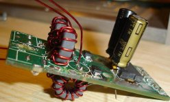
Anyway.... to keep things easy replace C10 with something bigger (more capacitance) but within the size parameters. Make sure of the polarity too..the striped side should be facing away from the chip. You can get panasonic FM's or FC's to fit nicely and they are very low ESR. I managed to pick up some NIC NRSK's 1000uf that are only 8mm diameter!...possibly the lowest ESR available!
Next you want to feed the positive 12V to the positive off-board cap and then onto the underside of C10. When you replace C10 leave a length of lead hanging out to solder too (again, to the positive side closest to the chip) the negative follows in paralell to the negative cap terminal and then onto the board where the old neg was attached. Done!
There are a multitude of ways you can do this but the closer the caps are to the chip/board then the lower the inductance created by the traces as they enter the chip...see one of my boards as to how close you can get em! Those are 0.1uf caps soldered to the bases of two 680uf FM's...then directly to the pins...inductance? What inductance?
Attachments
Re: Hey Dude back at ya!
He got those cores from me - tricky old Panomaniac.") I know the path to good RF and low DCR..... But Lost Cause did the winding (nicely, too) They should be 10uH.
I know the path to good RF and low DCR..... But Lost Cause did the winding (nicely, too) They should be 10uH.
sx881663 said:What inductance do they have and where did you get the cores?
He got those cores from me - tricky old Panomaniac.
I know the path to good RF and low DCR..... But Lost Cause did the winding (nicely, too) They should be 10uH.A question at the core of it.
panomaniac,
Thanks for the reply. I am bothered by the number of turns it takes to implement 10uh with most cores. This means more wire length of smaller diameter, not a good thing! Have you actually tested the cores to see what kind of inductance change you get with increasing current or just the number of amps before it is saturated? I haven’t tested any gray color cores myself.
Roger
A core question
D0Hbert,
Core ratings are determined by the individual manufacture and vary widely with differing materials. There are very few standards in relation to inductance per turn type of thing. To find out more you must actually measure it as you add turns or find out directly from that particular cores manufacture. Unfortunately they are very seldom identified in any way other than color.
I do think there is some conformity with color = characteristics but not enough to assume X number of uh per turn. At least this has been my experience.
Roger
D0Hbert said:Anyone got a site that gives a computation on the number of turns, or a mathematical computation, using he same kind of torroidal core but of different dimentions (height, inner and outside diameter of core)? Thanks
D0Hbert,
Core ratings are determined by the individual manufacture and vary widely with differing materials. There are very few standards in relation to inductance per turn type of thing. To find out more you must actually measure it as you add turns or find out directly from that particular cores manufacture. Unfortunately they are very seldom identified in any way other than color.
I do think there is some conformity with color = characteristics but not enough to assume X number of uh per turn. At least this has been my experience.
Roger
sx881663 said:Lost cause,
A couple of questions; where did you get the NIC caps? The inductors look interesting because of the low number of turns. What inductance do they have and where did you get the cores?
Thanks,
Roger
Hi Roger, as Panno said, he sourced the cores and was very kind to send me a few (knows his stuff!). Unfortunately I (my darling daughter) dropped one and broke it so I tracked down the little rings in the UK (RS-fairite type61). Are they exactly 10uh? No idea, I can't measure them! But they sound just great! Having said that I 'm going to take one with me to the local electronics store and measure it this weekend, although this wont test the load characteristics.
They do sound great though!
The NIC caps?...Well I actually got them as samples through work, along with all the rest of the components I have in my box!! They are very new so I don't think you can get them through commercial sources yet....maybe RS or Farnells?
maybe they aren't as good as I thought....
comparison
Cheers
Lee
Lostcause said:
Are they exactly 10uh? No idea, I can't measure them! But they sound just great! Having said that I 'm going to take one with me to the local electronics store and measure it this weekend, although this wont test the load characteristics.
Hi Lee, Maplin are very useful for testing inductors..I took my attempts in and they were way to high, unwound them till I was down to 3 turns for 10uH and 4 turns for 20uH. Can't see them being any good, haven't tried them yet as I have just finished building an Autocostuire 2020 amp, and it worked
..I will buy your suggestions from RS, what gauge wire did you use?
Barry.
audio1st said:
Hi Lee, Maplin are very useful for testing inductors..I took my attempts in and they were way to high, unwound them till I was down to 3 turns for 10uH and 4 turns for 20uH. Can't see them being any good, haven't tried them yet as I have just finished building an Autocostuire 2020 amp, and it worked
I will buy your suggestions from RS, what gauge wire did you use?
Barry.
WOW 3 turns for 10uh? & 4 fir 20!!!! what cores/wire did you use?
I just have 0.71mm magnet wire on mine...tried silver but could only get it in 1mm and it's too difficult to get a tight winding.
Maplin's, yup that's where I was going.....not looking forward to the results now......
Lostcause said:
WOW 3 turns for 10uh? & 4 fir 20!!!! what cores/wire did you use?
I just have 0.71mm magnet wire on mine...tried silver but could only get it in 1mm and it's too difficult to get a tight winding.
Maplin's, yup that's where I was going.....not looking forward to the results now......
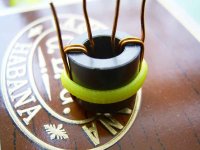
I used the ferrite rings from the power cable of the playstation. I only had 0.56mm winding wire and it was just a test to get some idea of how different cores affect the value.
Attachments
audio1st said:
I used the ferrite rings from the power cable of the playstation. I only had 0.56mm winding wire and it was just a test to get some idea of how different cores affect the value.
Ahhhh, those have a lot of ferrite in em! No wonder they give high values.
like the dual windings, I'm thinking along the same lines....you can just about get 24 wraps on the cores I use. It's just fitting them to the board that's a pain. I'm looking at my own board design at the moment, probably be rubbish but it's a good educator never the less.
Are you a Cigar man?.......
The higher the permeability of the core, the fewer turns you need. A type 77 would need very few turns, 3 or 4, for 10uH. The problem with type 77 (and many others) is that is not really suited to the frequency range of Tripath switching, though it might work well for amps or SMPS with a lower frequency.
For those of you who want the "inductor secret formula", here it is: L(nH) = N^2 *AL
Where L= inductance N=turns AL= Inductance index.
You have to know the inductance index of the core.
(Payment for the secret formula must be left in a brown paper bag in the phone box on the right, Piccadilly Circus, after midnight)
- Status
- This old topic is closed. If you want to reopen this topic, contact a moderator using the "Report Post" button.
- Home
- Amplifiers
- Class D
- Sonic Impact 5066 Parts List & Modifications