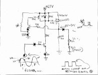
Part of this circuit that I am making resembles a class D circuit using a Mosfet device to drive a pulse of current into a load.
I am getting an occilation on the output voltage spike, when the device is driving current. I am sure I need a choke or an inductor some place in this circuit but I am not sure where excactly and of what value on account of I do not have much experience with this type of circuit topology. The circuit diagram and waveform sketches may help...
I am getting an occilation on the output voltage spike, when the device is driving current. I am sure I need a choke or an inductor some place in this circuit but I am not sure where excactly and of what value on account of I do not have much experience with this type of circuit topology. The circuit diagram and waveform sketches may help...
Attachments
...uhps!.... sorry I am no class D specialist...
In fact, I also do not fully understand your circuit and I have no clear indication for this oscillation.
But may be my brainstorming can help....
Do you see a oscillation also at the 50V/0V signal?
On the DC-rail? Do you supply this circuit from
SMPS which operates at 50kHz?
Do you have a current probe and can find the
loop in which the current is oscillating?
But there is one thing, which is critical IMHO.
You are supplying only positive pulses to the speaker.
....means, output signal contains a serious amount of DC.
Do you do this on purpose?
Bye
Markus
Possibly, the oscillations are related the confluence of such factors as the MOSFET directly driving a capacitor referenced to ground potential, the MOSFET's gate capacitance and other internal capacitances, and the 1.5k gate resistor. If you lower the gate resistor, does the frequency of the suboscillations increase? At the very least, a pair of output MOSFETs should be included instead of just one and the output fiter inductor should go between MOSFETs and output filter capacitors.
If you have only a single polarity power suppy, you should couple the speaker to the output through a large DC blocking capacitor as was done in audio amps in the old days. A 4700uF 63v one might work for a 4 ohm speaker load.
You could theoretically get by with the 4 ohm resistor replacing a lower MOSFET. But you should still place the 2.2uf capacitor after the inductor, and you should use the large DC blocking capacitor in the case of single rail power suppy use.
ChocoHolic said:...
But there is one thing, which is critical IMHO.
You are supplying only positive pulses to the speaker.
....means, output signal contains a serious amount of DC.
Do you do this on purpose?
Bye
Markus
Sorry for the misunderstanding, This circuit is a secondary current source for the output transistor and this is only the positive one, the negative side is an equal but opposite circuit. Zout resistor represents the output impedence of the amp.
The output stage is an emitter follower, drivers use +/- 50V reg.
The theory of operation is that I would like to push the outputs a little harder to get the peak and spikes of a full range audio signal and not exceed the breakdown of the "off" transistor, all using just two hi-current output devices. (and 2 Mosfet switches) I am using two common grounded power supplies (60Hz power transformers), one is +/- 36V @2A, and the other is +/- 63V @ 1.5A, with 15,000uF filter caps in order to handle the duty cycle. The circuit I have drawn drives just the NPN output with 50V. Switching diodes isolate the lower V power supply from the higher V one.
In other words, there is 35V on each output, until the signal is +16V or higher, then this circuit switches +50V onto the collector. (I may increase 16V this to 20V though) The PNP device still only has 35V on its collector. When the signal is -16V(or 20V) the negative circuit operates, -50V on the collector of PNP, and there would be only +35V on the collector of NPN. The Mosfet switches are never on at the same time, and this makes sure that 90V is not exceeded ever. I do not want to paralell output devices, just trying to push the envelope and still have plenty of Vce to limit nonlinearities. These devices are linear up to 7.1A. 28V peak would be 100RMS watts on 4Ohms.
When the Fet's switch on, there is NO effect on the audio signal, even at higher freq. But the occilations do affect it slightly.
This is not a common approach by amp designers, but it does seem to work well.

I know that this is kinda complicated, but it is interesting!
Chris
Bottom transistor turns on, pulls mosfet gate low (on), mosfet drain goes high, turns on npn transistor at very left, turns on pnp transistor at top which tries to short out gate drive and turn off mosfet. So, first and last transistor are having a fight. The time taken for the signal to travel around that loop kinda determines the frequency of your oscillation.
Circuit
This circuit is horribly ineffficient because the outout can only approach within about 10V or so of the supply. The FET is dropping at least 10V when turned on and is likely getting very hot, wiping out most of the advantages of class-f operation. That is why we use driver ICs like the IR2110 which drive the FET with a bootstrap circuit that supplies drive about 12V above the supply rail.
You must design the circuit so that the FET saturates. Otherwise, it will run very hot. As well, the top of the PWM output will be variable with transistor temperature.
Also, there is no supply rejection at all. Anything that happens on the power supply is passed on directly to the audio. The power supply has to be very well regulated.
Overall, this is a very primitive design. There are better circuits at www.schematicsforfree.mattsoft.net
Thanks for the info guys, it is very helpful.
Dan, the drain of the FET is the supply rails for the higher voltage current source for the collector, and is referenced to 50V. True that the FET is dissapating lots of heat, but since it is only turned on when the audio signal is above 20V, the duty cycle of this reg. circuit is less than 20%. Besides, I am expecting the higher supply voltage to ripple, this reducing the heat even more, but keeping 50V on the collector all the same, just when the signal is above 20V. This ripple will not affect the rest of my circuit unless it gets below 55V. The negative circuit is equal but opposite. With real full range audio, the spikes and peaks exist usually for a short time span anyway, more like a pulse circuit.
")
Dan, the drain of the FET is the supply rails for the higher voltage current source for the collector, and is referenced to 50V. True that the FET is dissapating lots of heat, but since it is only turned on when the audio signal is above 20V, the duty cycle of this reg. circuit is less than 20%. Besides, I am expecting the higher supply voltage to ripple, this reducing the heat even more, but keeping 50V on the collector all the same, just when the signal is above 20V. This ripple will not affect the rest of my circuit unless it gets below 55V.
The negative circuit is equal but opposite. With real full range audio, the spikes and peaks exist usually for a short time span anyway, more like a pulse circuit.Circuit Comments
Sorry but I erred in my analysis of this circuit. It is a P channel FET connected with the source to the supply and the drain to the load. I'm so used to seeing it the other way round with an N-Channel FET.
The citcuit should push the FET into saturation which should limit the heating. However, there will still be some heating from charging the 2.2uFd cap. However, the modulation scheme is very primitive and there is no supply voltage rejection.
This means that even if the signal is higher in frequency, there will be a major supply ripple component to it. Unless the supply is very well regulated.
Something like this could work as say a siren driver but I seriously doubt that there would be any fidelity to it.
By the way, the self oscillating idea is OK. The best sounding class D amps use a self oscillating setup.
However, one problem you have is that you are using the BE junction of transistors to act as comparitors in your switching. These have fairly soft "knees" which means that there is a linear region between on and off. As well, the point they turn on or off varies with temperature.
Then there are similar problems with the diodes in series with the transistor. These will limit the precision where you can switch. That is why the good class-D amplifiers use a precision comparitor like the LM319 for this purpose. The accuracy of the modulator and its stability will determine your sound quality. Even the LM311 ir LM339 is not good enough.
To get good Class D you need to switch between high and low at each point as fast as possible, with as little time spent in the in between levels as possible.
Re: Circuit Comments
I had originally designed this part of the circuit using a BJT because of cost, but it seemed to switch to slow and required much more current to drive. This tended to disrupt the audio just slightly. The FETs seem to work much better
Yes a P-channel hexFET, at least I think it is hex type. I had to go to some greif to get one, it cost me $10 as compared to $1 for the N-channel. The N-channel is for the negative side.) The signal from the FET does not actually drive the speaker though. It drives the collector of the output transistor----a dependent current source, which is a class AB biased BJT EF power amp, full range. The collector is switched from 35V to 50V during the short time that audio signal exceeds 20V in order to achieve a larger signal out, without breaking the other output device down and  It can only handle 90V, but is linear to 7A. Therefore I am not looking for acuracy from this "puse" circuit other than the switching time. The occilations I was experiencing were high enough freq. to shoot right through the hi-current (lower Vce breakdown) transistors and appeared on the peak of my audio signal.
The speaker that I am designing this circuit for is a 4 way speaker box, with internal passive filters. I have noticed that this load seems to have a higher impeadence for higer freq. than for lower ones and needs to have more voltage in order to achieve the power needed. I like highs. The AC load line changes with dynamic range. Extending the Vce effectively extends the linear operation of the AC load line that exists with higher frequencies, requiring more voltage and less current as opposed to lower freq. and while one output has Vc =50V(for less than 20% of time) the other Vc=-35V, and vise-versa. The max voltage possible on 'off' transistor is only 85V.
I don't want to parralell output BJT devices.
As for supply rails ripple voltage I expect that this will happen, even with 15,000uF filter caps, but since this circuit is a regulator at 50V, It should not affect the circuit.
I hope to do some more testing tomorrow.
Chris
I had originally designed this part of the circuit using a BJT because of cost, but it seemed to switch to slow and required much more current to drive. This tended to disrupt the audio just slightly. The FETs seem to work much better
Yes a P-channel hexFET, at least I think it is hex type. I had to go to some greif to get one, it cost me $10 as compared to $1 for the N-channel.
The N-channel is for the negative side.) The signal from the FET does not actually drive the speaker though. It drives the collector of the output transistor----a dependent current source, which is a class AB biased BJT EF power amp, full range. The collector is switched from 35V to 50V during the short time that audio signal exceeds 20V in order to achieve a larger signal out, without breaking the other output device down and It can only handle 90V, but is linear to 7A. Therefore I am not looking for acuracy from this "puse" circuit other than the switching time. The occilations I was experiencing were high enough freq. to shoot right through the hi-current (lower Vce breakdown) transistors and appeared on the peak of my audio signal. The speaker that I am designing this circuit for is a 4 way speaker box, with internal passive filters. I have noticed that this load seems to have a higher impeadence for higer freq. than for lower ones and needs to have more voltage in order to achieve the power needed. I like highs. The AC load line changes with dynamic range. Extending the Vce effectively extends the linear operation of the AC load line that exists with higher frequencies, requiring more voltage and less current as opposed to lower freq. and while one output has Vc =50V(for less than 20% of time) the other Vc=-35V, and vise-versa. The max voltage possible on 'off' transistor is only 85V.
I don't want to parralell output BJT devices.
As for supply rails ripple voltage I expect that this will happen, even with 15,000uF filter caps, but since this circuit is a regulator at 50V, It should not affect the circuit.
I hope to do some more testing tomorrow.
Chris
After further experimenting, I think I am going to go a different route with the switching FET regulator. An inductor did take some of the occilations out, but only the higher frequencies, there is still some occilations left.
I am going to try using the FET in a source follower configuration instead of a feedback loop configuration. By referencing the gate to 55V zener reference voltage, there should be about 50V on the source, it doesn't have to be perfect as it may change slightly with varying current. Without the feedback loop it shouldn't occilate. The circuit is less complex anyway.
I am going to try using the FET in a source follower configuration instead of a feedback loop configuration. By referencing the gate to 55V zener reference voltage, there should be about 50V on the source, it doesn't have to be perfect as it may change slightly with varying current. Without the feedback loop it shouldn't occilate. The circuit is less complex anyway.
sweeeeeeet
in scraping the feedback regulator loop for a simpler source follower, I have eliminated the occilations, but to drive the capacitance of the FET up to 20KHz I found that I need to have a lower impeadence for the gate drive maybe a smaller power transistor. This helped with the phase change of the output with relation to the input. That is one major criteria for this circuit.
in scraping the feedback regulator loop for a simpler source follower, I have eliminated the occilations, but to drive the capacitance of the FET up to 20KHz I found that I need to have a lower impeadence for the gate drive maybe a smaller power transistor. This helped with the phase change of the output with relation to the input. That is one major criteria for this circuit.
- Status
- This old topic is closed. If you want to reopen this topic, contact a moderator using the "Report Post" button.
- Home
- Amplifiers
- Class D
- Need some help from you class D experts