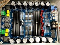
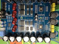
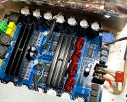
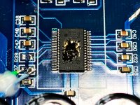
I had a free project chassis so I got this cheap TPA3116D2 board on eBay from China. I was surprised at how well it was put together, and its sounds is not bad. I need advice on upgrading the output filters. It has quite a bit of hiss. As usual, my intent is to take it to the next level. To be candid, for $32, there is hardly anything complain about.
Attachments
Last edited:
Gain is set to max on the 3116D2, that is 36dB, I can set it to 20 dB. Since these are SMD resistors, 20dB is about the only option I have, there are two other steps in between, but I do not have the resistors for those. Both chips are set to master mode.
Thanks.
Thanks.
Attachments
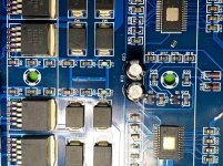
The hiss is definitly coming from the onboard preamp (4x opamp so14), combined with a to high gain from the tpa3116. I'd first lower the gain on the TPAs.
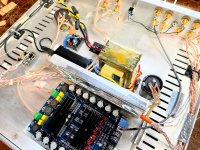
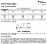
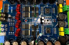
Thank weissi, you are a genius and knew exactly the solution. I followed the TI datasheet and brought the gain down to 20dB from 36 dB. So quiet at turn on, that I wondered if amp was no longer working. It is dead quiet now, no hiss, not even a hint of it. And turn on/off pops almost acceptable. I had to wire in the R39 (R1) 5.6K resistors as no SMD tools or resistors available here at my bench. R37 (R2) is left open (removed). Input cap already at 1 uF.
The sound is very hi-fi now.
Next task is to mute board before on/off. Have to obtain a switch first. There is no trace on the pins 2, so it will be a bit of challenge to solder the small wires for the switch between SDZ (2) and GND (9), I think...
Attachments
Last edited:
The chip doesn't necessarily DEMAND the exact 5.6kohm resistor value there; at least on the small PBTL mono boards, the 20dB setting is achieved simply by removing the top resistor from that resistive divider.
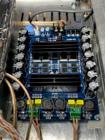
Also, very interesting that they included four boost-converter (XL6019) chips on board. I guess that's how they achieve the "car amp" status, without lying. Kinda wonder what the beat frequencies might be, between them.
Also, very interesting that they included four boost-converter (XL6019) chips on board. I guess that's how they achieve the "car amp" status, without lying. Kinda wonder what the beat frequencies might be, between them.
- Home
- Amplifiers
- Class D
- Has anyone tried this TPA3116D2 X2 board from China?