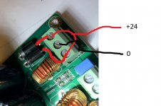
Hello, I purchased a class D amp that advertised as taking a 24VDC 10amp input. I was expecting it to come with a 2 terminal power input labelled + and - but instead it is a 3 terminal and labelled VCC GND VCC and there are no instructions. I have attached a picture below. I connected the power supply + to the left VCC and the - to the GND and it powers up and works (and is actually way more powerful then I was expecting). Unfortunately there is a lot of hiss when there is no input. I am trying to figure out what the problem is and so one option I wanted to try was replace the power supply. I do not have another 24V power supply but I do have a couple of 12V. Does anybody have a suggestion of what the purpose of the extra VCC terminal would be? Do you think this is so I could connect one 12V PS between the left VCC and GND and then a second 12V PS between the the right VCC and GND in order to get 24V?
thank you
thank you
Attachments
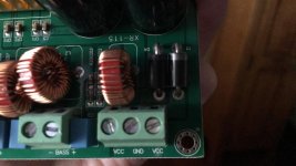
Does each VCC input go to the anode of each of those two diodes? If so then both should be used. The diodes would be for polarity protection and two in parallel to get more current handling.
As always... without circuit details it is all guess work based on interpretation of what we see.
As always... without circuit details it is all guess work based on interpretation of what we see.
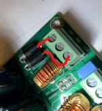
Unfortunately it appears to be a multilayer pcb. There are no traces on the bottom and the traces on the top do not seem to directly connect to many of the components. The cathodes of the two diodes appear to have no connection on the top or bottom of the pcb. I have attached a couple of pics from different angles.
Attachments
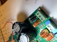
I thought they might have been like this. You would need to check the continuity with a meter to be sure. The diode leads will connect to the copper print even though there is no obvious solder on the top. The hole will be plated through from where it is soldered underneath.
If there is doubt then you should contact the seller and ask for clarification.
If there is doubt then you should contact the seller and ask for clarification.
Attachments
Yes, you are absolutely correct, I just checked continuity and it is connected exactly as you have drawn it. The VCC's are connected to the anodes of the diodes on their side. There is also continuity between the two cathodes. I definitely contacted the seller but sadly they said they could not help me. So does this mean I should be connecting the + and - to each of the VCC and then nothing connects to the GND?
Thank you very much guys. I hooked it up that way but it seems to behave the exact same way. I managed to get a nice Lamda regulated power supply and hooked it up and I am still getting the hiss. So now I have eliminated the input wiring, the power supply and the speaker wire as the source of the hiss so I guess the only thing left is that it must be the amplifier itself. Is it possible that it is because the amp is just too high powered for the speakers or is it more likely that it is just a bad amp? The speakers are 16W 4ohm that I have taken apart out of a soundbar and the sub is 30W 2ohm. The amp is 240W. I selected this amp because it was one of the few I could find that could power a 2ohm sub, most were saying 4-8ohm subs only. I was surprised when I hooked it all up and it is so loud if I just turn the volume knob a tiny sliver. Definitely this will not be convenient for volume control but I am not expecting to adjust the volume very often.
To determine if the amp is noisy you must run it with the audio input shorted out. That's standard practice on any amp. In that state it is as quiet as its going to get.
You should be easily able to alter the apparent input sensitivity with nothing more than a couple of resistors as an attenuator at the input. That will allow the volume control to work normally over whatever amount of rotation you wish.
You should be easily able to alter the apparent input sensitivity with nothing more than a couple of resistors as an attenuator at the input. That will allow the volume control to work normally over whatever amount of rotation you wish.
Scope the outputs and show result here.Thank you very much guys. I hooked it up that way but it seems to behave the exact same way. I managed to get a nice Lamda regulated power supply and hooked it up and I am still getting the hiss. So now I have eliminated the input wiring, the power supply and the speaker wire as the source of the hiss so I guess the only thing left is that it must be the amplifier itself.
IF there is some ultrasonic oscillation or instability, we Humans can´t hear it directly, but often its "artifacts" (interactions with other elements, which are non linear) appear as "hiss" to us.
Look and share.
Try shunting the inputs to the signal ground using a resistor and always use shielded cables for the small signals. The output/power and the inputs are on opposite sides of the PCB, aren't they?
The speaker connections and the power supply are on the back of the PCB and the signal input is at the exact opposite corner right next to the volume knob. So they are as far apart as they can be.
To determine if the amp is noisy you must run it with the audio input shorted out. That's standard practice on any amp. In that state it is as quiet as its going to get.
You should be easily able to alter the apparent input sensitivity with nothing more than a couple of resistors as an attenuator at the input. That will allow the volume control to work normally over whatever amount of rotation you wish.
I just tried shorting the right and left signal inputs to the input ground and powered it on and the hiss is about the same. So I guess that means its just always going to be there?
Scope the outputs and show result here.
IF there is some ultrasonic oscillation or instability, we Humans can´t hear it directly, but often its "artifacts" (interactions with other elements, which are non linear) appear as "hiss" to us.
Look and share.
I have an old tube scope but I can't seem to get it to work. I am a backer on that Pockit Pro but unfortunately they are way behind on production so I am currently "scopeless"

I just tried shorting the right and left signal inputs to the input ground and powered it on and the hiss is about the same. So I guess that means its just always going to be there?
Well, one (more) thing you can is to place the whole thing inside a metal cabinet (and of course connect this cabinet to ground). Now, if the hiss happens to remain even after all this, then there may be something (fundamentally) wrong with the amplifier - gain structure, PCB layout, grounding etc. could be anything, and would require the complete circuit diagram/layout to assess.
Not very related to the topic, but I find it hard to believe that an amplifier power stage is laid out across so many layers which, in my opinion, is not a very good practice when it comes to power electronics.
I just tried shorting the right and left signal inputs to the input ground and powered it on and the hiss is about the same. So I guess that means its just always going to be there?
I think it does I'm afraid.
To determine if the amp is noisy you must run it with the audio input shorted out. That's standard practice on any amp. In that state it is as quiet as its going to get.
You should be easily able to alter the apparent input sensitivity with nothing more than a couple of resistors as an attenuator at the input. That will allow the volume control to work normally over whatever amount of rotation you wish.
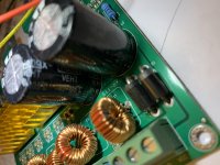
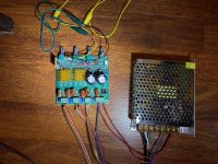
Attached is a picture of how I tested it with the audio input shorted out. I just connected jumpers from the Lin and Rin to the Gnd. Is that correct? The black wire is the ground, Red and Yellow are the Rin and Lin. In the bottom right you can see where I have connected both Vcc's to the + of the PS (red wires) and the Gnd to the - of the PS (blue wire).
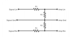
In order to build the attenuator that you are referring to, is the diagram that I have sketched up here correct? Do you have any recommendations for what I should use for R1 and R2?
thank you very much for all your help.
Attachments
That's fine although I would have shorted the pins on the board to get the lowest possible noise result. Wires like that could pick up stray hum and noise but if the hiss was unchanged then it is going to be the way it is unfortunately.
The attenuator is correct and I would use something like 10k or 15k for R1 and then whatever you find works best for R2.
If you make R1 and R2 the same value (either 10k or 15k) then you cut the signal level in half. Based on how you describe how loud it is for just little volume control rotation I would try something like a 2k2 for R2 and then work up or down from there.
- Home
- Amplifiers
- Class D
- How to connect power to a Class D amp board?