The smaller ELE caps are measuring OL sounds like the low voltage rails feeding the IRS2092 are shorted. This can be confirmed by measuring resistance from IRS2092 Pin 2 (ground) to Pin 1 (~+5V,VAA) and Pin 2 to Pin 6 (~-5V,VSS). This should be measured with the output board not connected to the SMPS.
If the above is confirmed, we need find the source of the short. It could be the IRS2092. If you have the equipment to desolder the IC, I would start by removing it and repeating the above test on the IC out of circuit.
If the LV rails are still shorted, the two 5.1V zener diodes (D15, D16) used to regulate the +\-5V rails could be shorted. Remove from PCB to test.
If the LV rails are still shorted on the output PCB, one or more of the ten small signal NPN and PNP transistors could be shorted. Check the PN junction diode drops on the PCB first. If you find a short, remove the transistor from the PCB and retest to ensure there wasn't another shorted transistor on the PCB shorting out the one you first tested.
When you find the culprit, I suggest digging a little deeper to try and understand what happened before trying to power it back up.
Although the OP didn't specifically confirm this, I am assuming OP determined the problem was the output board by testing the good output board with the SMPS and Control board from the bad amp? This will have confirmed that the SMPS is not also at fault.
Sadly, the IC pins were not shorted, measured similar to the working unit's. On the positive side, I did very carefully power them both up and the smps is confirmed ok, both 61V rails and the supply to the input board was measuring as the working one's.
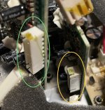
I did want to isolate what board is failing but since the manufacturer decided to flip both sides of interconnect cable 180° (correctly, the 8pin pcb terminals) somewhere in their revisions, I can't connect the bad (?) power stage to the working amp's input board:

So, next steps during the week. I'm adding a sine and try to follow that signal, hopefully without having to power up anything.
Also checking transistors as someone recommended above to try to find shorts, or differences (having the pots in the same positions help [emoji51]).
Then, I'm close to calling it off, judging by other threads, these amps seems to easily fail, so who knows how long it will be before it fails again in that environment. External amplification seems way better, just sealing the hole proper and adding binding posts sounds so much more safe and long term robust.
I'm actually in the running for scoring a used (by home gamer) Crown CDi 1000 (2x500@4ohm or 1000W bridged, 0.5%THD) that even has some PEQ built in..
D
Deleted member 148505
If you can identify the purpose of each wire in the PCB header of the amp module, then you can easily isolate if the problem is with the amp module or with the control / preamp module.
Look for the ff:
audio input signal
mute signal
dc output protect signal
+/-5V DC aux for housekeeping supply
If the problem is with the amp module, you can replace it with another module by just getting the audio signal. You will lose idle power saving though if you can't identify the wirings.
(Shameless plug) We have a suitable module for that: <link> You just need to add speaker protect and bulk supply capacitors.