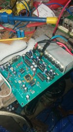
It was developed from the Class D Filter Less used in the PAM8610 PAM8403, but my method allows for voltages up to 100VDC. and sound very good like TUBE .
Log into Facebook
Log into Facebook
Log into Facebook
V off set =<0.07VDC=<0.07VAC
2CH
[Can be operated at VDD voltage from 1V to 200V, very clean input signal is required.]
Log into Facebook
Log into Facebook
Log into Facebook
V off set =<0.07VDC=<0.07VAC
2CH
[Can be operated at VDD voltage from 1V to 200V, very clean input signal is required.]
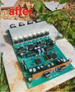
Attachments


Last edited:
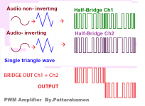
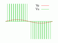
Output voltage with no sound Average voltage is lower than 0.07VDC and VAC when average voltage is on. The value corresponding to the analog signal is given. Where the output signal is PWM, the speaker will work according to the audio signal immediately, can not work as a square wave. and the speaker unit will not be damaged due to the reverse waveform following the Class D audio signal. Normal type cannot use PWM directly.
Attachments

Last edited:
The first I built There is a video on Youtube.
Filterless Class D Amplifiers - YouTube
Filterless Class D Amplifiers - YouTube
The speakers will no longer operate at those high frequencies in the waves I created. I for example At a frequency of 230kHz 100V with a 1% duty cycle, you get an voltage of 1V average, so the speaker will operate at its average output. Cannot move according to square wave contract But the speaker can move according to the duty value.
This technology has already been implemented in the PAM8403 and PAM8610. My circuit is more efficient than being able to set the V offset =>20mV . The standby current is less than 65mA.
This technology has already been implemented in the PAM8403 and PAM8610. My circuit is more efficient than being able to set the V offset =>20mV . The standby current is less than 65mA.
Attachments
In the early days of class D, a power amp came into the workshop with the complaint that it did not sound right.
When the tech switched it on, the workshop radio died, and the radio microphone tech came into the workshop to locate the source of a very high powered RF signal which was swamping his spectrum analyser.
One of the post recovery inductors was dry jointed, and the amp was pushing out a couple of hundred watts of RF.
Those chips are a few watts and you are supposed to use a filter unless the leads to the speaker are short (you are responsible for EMI compliance) - at high powers you need filtering to be legal for EMI - or at least you'll need to figure out how to shield everything well enough to pass compliance testing.
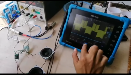
This is an unfiltered Class D test video on YouTube, voltage 65VDC, both 2CH, standby current 0.05A. This test try 1CH float CH2.
Class D No coli !! Test 65VDC 235kHz - YouTube
Cap value 101, I used 501 instead.
Class D No coli !! Test 65VDC 235kHz - YouTube
Cap value 101, I used 501 instead.
Last edited:
If you want the sound of tube based output stage, why not try a wideband 1:1 output transformer?
You can get pretty close with matching transformers used in distributed sound systems, if you get the right one. I got a couple "Atlas" T-11s, which have a primary as low as 45 ohms - with 4, 8, and 16 secondaries. Only 15W, but it's about the sound, not the power, right? I assume if you put an 8 ohm speaker on the 16 ohm output, 45 ohms at the input drops correspondingly to 22.5...
If it did something favorable, you could get a manufacturer to build one more suitable. I assume the transformer will also "block" RFI via it's frequency response falloff, in a way that's "better than nothing", allowing normal speaker cable length.
FWIW, and good luck with your project!
Last edited:
The system I built is more efficient than an LC because it directs the output current that the MOSFET can do directly to the loudspeaker according to the sound signal Because it will not lose current in the PWM filtering. The standby current is also lower.
. but may not be suitable on longer speaker cables, so this system may be suitable for use in an active speaker cabinet. whether the subwoofer or general speaker cabinet may have to install This type of amplifier is built into the cabinet to prevent signal leakage.
. but may not be suitable on longer speaker cables, so this system may be suitable for use in an active speaker cabinet. whether the subwoofer or general speaker cabinet may have to install This type of amplifier is built into the cabinet to prevent signal leakage.
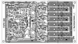
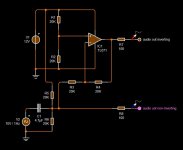
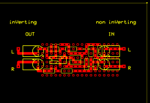
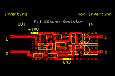
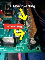
I have developed an audio inverting circuit. using voltage G/+12VDC that is already in the PCB This eliminates the need to separate the +/-15 pressure again.
TL072CP
+12 to pin8 GND pin4.
TL072CP
+12 to pin8 GND pin4.
Attachments
Last edited:

Its sound is satisfying. If you don't believe me, listen to this video I made.
Class D NO Coil filter!! [Full PWM to speaker] - YouTube
Class D NO Coil filter!! [Full PWM to speaker] - YouTube
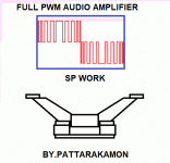
- Home
- Amplifiers
- Class D
- Class D (no filter coil )Full PWM to speaker