Oh, no river will flow red , this is the Internet. ")
No blood spilled no matter what, at worst a few spilled electrons
Notvthat easy, it involves adding components and some neurosurgey.
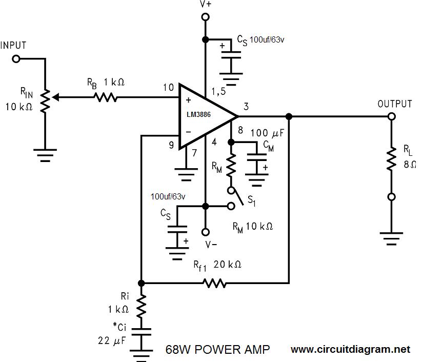
For reference, compare the LM3886 (a VERY similar chipamp) double and single supply versions.
They added ground reference, half supply biasing, changed the NFB reference point and added input and output coupling capacitors, the output one is substantial.
Regular split supply (like yours):
Modded for single supply:

not easy because it involves cutting tracks , rerouting them, tack soldering components on board, etc.
Technically doable, but ........
Sincerely, I´d suggest pick one of 2 options.
1) trade 48V supply for 2 x 24V ones, use them in series, center tap is ground (best).
2) buy a new amp specifically designed for single +48V (similar to LM3886 I posted above) or a Class D BTL type one, alhough it will put out a lot of power (way over 100W) an not sure your SMPS can handle that.
No blood spilled no matter what, at worst a few spilled electrons
Operate the amplifiers from a single supply.”: do you mean hook up the 0 and 48V to the ac inputs of the amps and not connect the 0 of the amps?
Notvthat easy, it involves adding components and some neurosurgey.
For reference, compare the LM3886 (a VERY similar chipamp) double and single supply versions.
They added ground reference, half supply biasing, changed the NFB reference point and added input and output coupling capacitors, the output one is substantial.
Regular split supply (like yours):
Modded for single supply:
not easy because it involves cutting tracks , rerouting them, tack soldering components on board, etc.
Technically doable, but ........
Sincerely, I´d suggest pick one of 2 options.
1) trade 48V supply for 2 x 24V ones, use them in series, center tap is ground (best).
2) buy a new amp specifically designed for single +48V (similar to LM3886 I posted above) or a Class D BTL type one, alhough it will put out a lot of power (way over 100W) an not sure your SMPS can handle that.
I didn't mention the possibility of BTL using two TDA7293s because that could become expensive and potentially wasteful. However, if that is an option (for the OP), it could also provide lower distortion with higher power, apart from the convenient single supply.
Though many Class-D designers are also very good SMPS designers, modification of the SMPS for a bipolar output is something that would be more relevant if presented within the power supply sub-forum. The OP (noob), please note that it's possible for moderators to move the thread to a more relevant section of the forum, in case you would like to move along those lines.
Though many Class-D designers are also very good SMPS designers, modification of the SMPS for a bipolar output is something that would be more relevant if presented within the power supply sub-forum. The OP (noob), please note that it's possible for moderators to move the thread to a more relevant section of the forum, in case you would like to move along those lines.
Last edited:
single supply
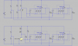
This can work but you need to separate the input and output ground. The input bias must not be exposed to the speaker return ground. Return the speaker ground to a separate pair of capacitors, not connected to the amp ground. But I notice on the data sheet this chip has some mute and standby circuit that returns to ground, which will require some DC ground current. So you will require -24V regulator wrt +48 to hold ground to 0V, assuming that cct draws positive current. That could be a pass transistor, a 7924, a 7912 wired like a LM337, or a LM337.
This can work but you need to separate the input and output ground. The input bias must not be exposed to the speaker return ground. Return the speaker ground to a separate pair of capacitors, not connected to the amp ground. But I notice on the data sheet this chip has some mute and standby circuit that returns to ground, which will require some DC ground current. So you will require -24V regulator wrt +48 to hold ground to 0V, assuming that cct draws positive current. That could be a pass transistor, a 7924, a 7912 wired like a LM337, or a LM337.
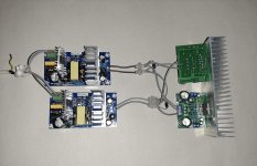
Attachments
Thanks guys, very interesting stuff!
JMFahey: this neurosurgery sounds tempting but might indeed be a bridge too far
Not sure if 2 supplies will work. I tried to connect this supply between the 0 and + on the TDA board and my smtp still trips...
NV: good to know, in case I cannot find my topic anymore
SteveU: this looks next level. Just to make sure that I understand correctly:
The upper circuit shows the principle of a separate ground but cannot be used due to the standby and mute circuits.
Going this way means that I have to cut the ground track on the TDA board between the input and speaker connections.
The LM337 can only handle 1.5 A but this is ok since it only serves the input signal.
All correct?
I have already replied to this problem before, read:
Need help with TDA7294
Only difference would be that in the old post they had only a single +24V so one option was to buy a TDA2030 single supply board for $5-7 , not an option with +48V
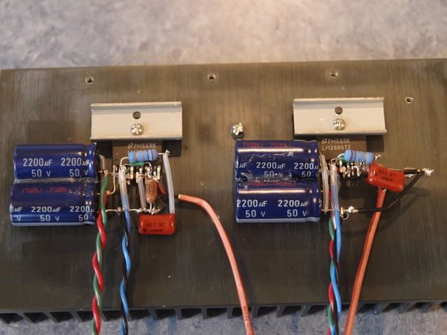
Plan B but not for the faint of heart would be to pull TDA7294 from your PCB and buikd the single supply vrsion "dead bug style" , meaning NO PCB
Crazy as it sounds, it´s sometimes done with its cousin LM3886
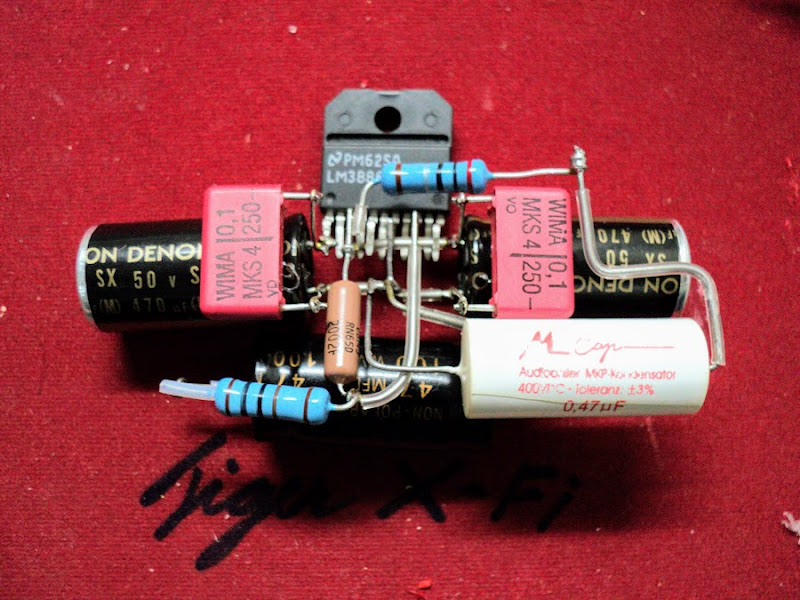
Point-to-Point LM3886
Not hard to do but a couple years experience making hippie jewelry at some beach will certainly help
Point-to-Point LM3886

Need help with TDA7294
Only difference would be that in the old post they had only a single +24V so one option was to buy a TDA2030 single supply board for $5-7 , not an option with +48V
Plan B but not for the faint of heart would be to pull TDA7294 from your PCB and buikd the single supply vrsion "dead bug style" , meaning NO PCB
Crazy as it sounds, it´s sometimes done with its cousin LM3886
Point-to-Point LM3886
Not hard to do but a couple years experience making hippie jewelry at some beach will certainly help
Point-to-Point LM3886
Well, if you're into crazy methods, here's another one for you. Attached picture shows three single-ended amplifiers (like a 3-phase inverter) with three speakers connected between the phases (like a delta-connected 3-phase motor). Only a single supply required, enjoy !
The surround channel, obtained according to the Dolby Surround matrix, is to be placed behind the listener (optional).
Note that this thread was actually over a long time ago, the shortest and straightest answer being post #2 by rayma. The only silver lining is that the OP (and anyone else reading) could have some unconventional (and interesting) ideas like the ones above.
Last edited:
not exactly
No you do not make any PCB cuts. Just wire the speaker return (negative) to the external caps (only, not resistors etc.) and leave the module speaker (-) terminal unused. The bias circuit (resistors etc) still connects to the amp ground. This is actually the way an amp should be wired, ie return the speaker to the power supply and not to the amplifier module. This keeps the heavy speaker current off the amplifier module ground.
Simply wiring the speakers this way may be enough to make the resistor circuit work and maybe not, ie possibly no need for the transistor or LM337. The amp will drive the voltage between the caps to something close to 0VDC, but the slight offset will feedback to the input and latch up if it is not separated.
Not exactly. The two circuits are roughly equivalent and should provide enough current for the mute and standby circuits, vs just a pair of resistors that probably doesn't.SteveU: this looks next level. Just to make sure that I understand correctly:
The upper circuit shows the principle of a separate ground but cannot be used due to the standby and mute circuits.
Going this way means that I have to cut the ground track on the TDA board between the input and speaker connections.
The LM337 can only handle 1.5 A but this is ok since it only serves the input signal.
All correct?
No you do not make any PCB cuts. Just wire the speaker return (negative) to the external caps (only, not resistors etc.) and leave the module speaker (-) terminal unused. The bias circuit (resistors etc) still connects to the amp ground. This is actually the way an amp should be wired, ie return the speaker to the power supply and not to the amplifier module. This keeps the heavy speaker current off the amplifier module ground.
Simply wiring the speakers this way may be enough to make the resistor circuit work and maybe not, ie possibly no need for the transistor or LM337. The amp will drive the voltage between the caps to something close to 0VDC, but the slight offset will feedback to the input and latch up if it is not separated.
Last edited:
What is your TDA filter capacitor? Adding a lot of decoupling capacitance can de-stabilise SMPS' control loops.
If the problem doesn't disappear even when speakers are disconnected, I suggest you have the thread moved to the power supply forum to get better response(s). After all, nothing about your issue is class-D anyway, don't you think?
If the problem doesn't disappear even when speakers are disconnected, I suggest you have the thread moved to the power supply forum to get better response(s). After all, nothing about your issue is class-D anyway, don't you think?
Last edited:
Try checking for an internal short from V+ to V-/GND/Vout of the ICs. Amplifier ICs sometimes blow if they oscillate at high frequencies (due to a poor control loop etc.) where considerable amounts of shoot-through happen in the output transistors.
It's also possible that someone deceived you with fake ICs in which case, you better check everything well before you discard the boards. You may also put up a question in the chip-amps forum to find out if there's a way out.
It's also possible that someone deceived you with fake ICs in which case, you better check everything well before you discard the boards. You may also put up a question in the chip-amps forum to find out if there's a way out.
If I got fake chips then only option is to toss them away, or?
Try changing the ICs, as it's quite possible that the circuit/PCB is correct but the chips that were put in were fake and the seller simply decided to pass that on to the customer (i.e. you).
However, note that the above is based on the assumption that other components (resistors, capacitors etc.) are not fake.
Last edited:
In theory I see no insurmountable problems in using a TDA7294 or similar Chip Amp ( TDA, LM, STK and so on) with a single power supply, These ICs work as power op-amps. As suggested, the signal mass must be separated from the power mass. In the case of standby or mute functions, either an additional voltage reference is used or, more simply, a high voltage supply OP Amp, or a transitor circuit, can be used, in order to further separate the signal ground from that of the controls. . As for the power mass, the loudspeaker can be connected in the middle of the series of two large electrolytic capacitors, as suggested by others, it decreases the rejection ratio but it is feasible, it also depends on the capacitance of the capacitors, or a BTL configuration is used (TDAx2) or parallel + BTL (TDAx4) with load also sized according to the supply voltage. With BTL the return current don't need ground to come back. If the power supply is unable to support the necessary current, you can think of a limiter
Last edited:
- Home
- Amplifiers
- Class D
- overcurrent protection